
PE electric smelting sleeve protection device and installation method

A protection device and installation method technology, applied in the direction of pipeline protection, pipeline connection arrangement, pipe/pipe joint/pipe fitting, etc., can solve problems such as distortion, air leakage, deformation, etc., achieve convenient and simple installation and use, ensure bonding strength, The effect of taking up less space

Pending Publication Date: 2021-11-12
青岛泰能高新燃气有限公司
View PDF0 Cites 0 Cited by
  • Summary
  • Abstract
  • Description
  • Claims
  • Application Information

AI Technical Summary

Problems solved by technology

[0006] Aiming at the deficiencies in the prior art, the present invention provides a PE electrofusion sleeve protection device and installation method, which not only solves the problem of distortion, deformation, and air leakage of the PE electrofusion sleeve due to settlement and external force. It also reduces the difficulty and cost of early construction and later repair and maintenance, which is of great significance to the safe operation of urban gas pipeline networks

Method used


Image

  • PE electric smelting sleeve protection device and installation method
  • PE electric smelting sleeve protection device and installation method
  • PE electric smelting sleeve protection device and installation method

Examples


Embodiment Construction

[0030] The technical solutions in the embodiments of the present invention will be clearly and completely described below in conjunction with the drawings in the embodiments of the present invention. Apparently, the described embodiments are only some, not all, embodiments of the present invention. Based on the embodiments of the present invention, all other embodiments obtained by persons of ordinary skill in the art without making creative efforts fall within the protection scope of the present invention.

[0031] In describing the present invention, it should be understood that the terms "center", "transverse", "longitudinal", "upper", "lower", "front", "rear", "left", "right", " The orientations or positional relationships indicated by "vertical", "horizontal", "top", "bottom", "inner" and "outer" are based on the orientations or positional relationships shown in the drawings, and are only for the convenience of describing the present invention and Simplified descriptions...


PUM


Abstract

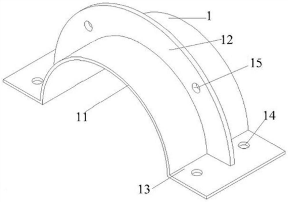
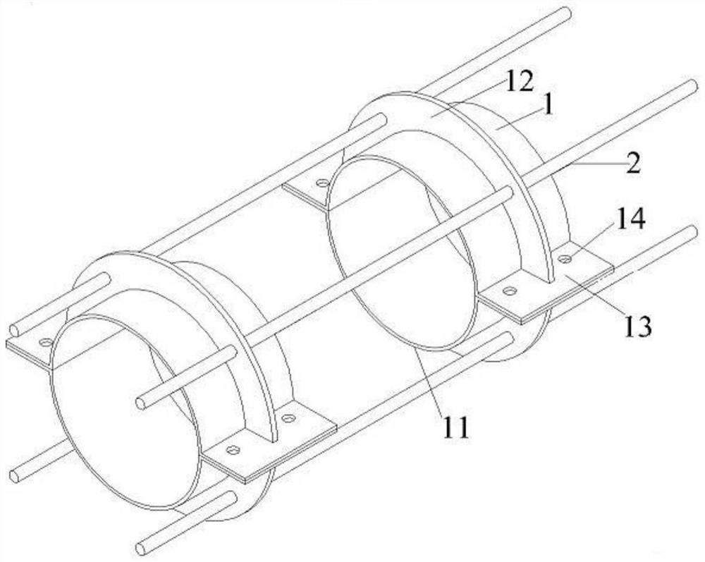
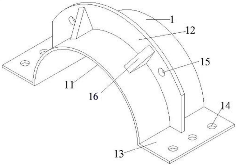
The invention relates to a PE electric smelting sleeve protection device and an installation method, and belongs to the technical field of fuel gas conveying. The PE electric smelting sleeve protection device is used for protecting a PE electric smelting sleeve from distortion and deformation due to the influence of external force and ensuring safe fuel gas conveying. The PE electric smelting sleeve protection device comprises at least two sets of detachable protection device assemblies, and the protection device assemblies are of annular cylindrical structures and fixedly arranged on PE pipelines at the two ends of a PE electric smelting sleeve in a sleeving mode through metal screws and fixing bolts. According to the PE electric smelting sleeve protection device, under the conditions of sedimentation and external digging force, especially in foundation soft environments such as pit filling and water filling, the external force borne by the PE electric smelting sleeve protection device can be dispersed to PE pipelines at the two ends of the PE electric smelting sleeve, the PE electric smelting sleeve is effectively protected to be in the state that the PE electric smelting sleeve is not subjected to external stress or is subjected to less external stress, the bonding strength of the welding position of the PE electric smelting sleeve and the PE pipelines is guaranteed, the air leakage problems of distortion, deformation and the like caused by sedimentation and external force of the PE electric smelting sleeve are solved, and the PE pipelines are protected.

Description

technical field [0001] The invention belongs to the technical field of gas transportation, and in particular relates to a PE electrofusion sleeve protection device and an installation method. Background technique [0002] Compared with traditional metal pipes, PE pipes are widely used in urban gas pipeline networks because of their corrosion resistance, maintenance-free, convenient construction, and good air tightness. However, PE pipes also have certain deficiencies during use, especially after being subjected to external pressure during construction, they are easily damaged and have poor ductility. [0003] In the prior art, PE pipes are usually protected by PE electric fusion sleeves. The working principle of PE electric fusion sleeves is to heat the resistance wires inside the PE electric fusion sleeves to melt the PE pipes connected at both ends of the sleeves. The end PE pipes are butt welded together. Specifically, the resistance wire is pre-embedded in the pipe wall...

Claims


Application Information

Patent Timeline
Patent Type & Authority Applications(China)
IPC IPC(8): F16L57/02F16L47/03F16L55/00
CPCF16L57/02F16L47/03F16L55/00
Inventor 尹智才耿坚崔元杰赵兴旺李卓柯牛兆祥孙云豪黄星汉穆玉龙张正昊黄志雄
Owner 青岛泰能高新燃气有限公司
Learn More