

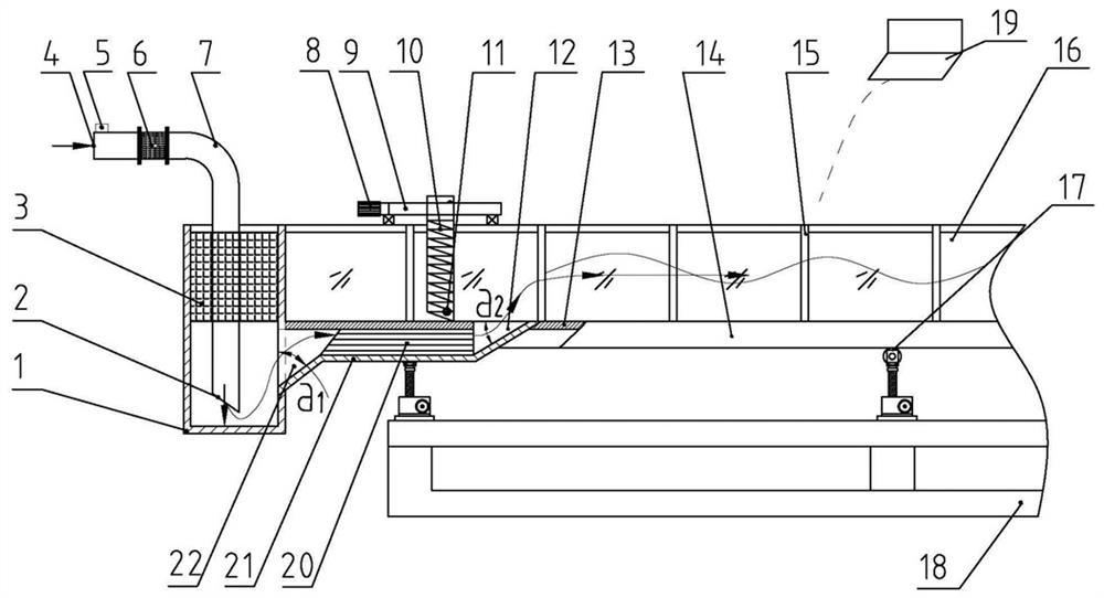
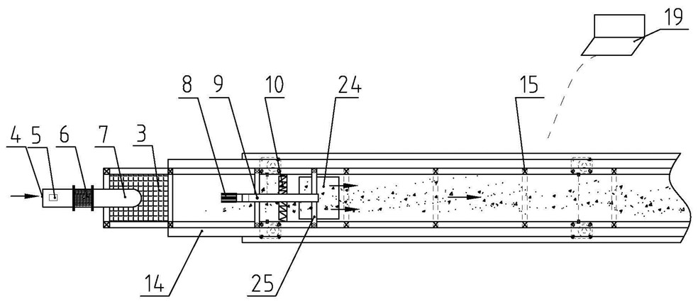
A wave flow generation system with a rear-mounted water tank at the outlet
A rear-mounted, outflow port technology is applied in the field of wave flow generation system for post-outlet tanks, which can solve the problems of destroying the shape of waves, the inability to generate waves and currents at the same time, and violating the principle of infinitely long use of straight-line water tanks. To achieve the effect of meeting the test requirements
- Summary
- Abstract
- Description
- Claims
- Application Information
AI Technical Summary
Problems solved by technology
Method used
Image

Examples
Embodiment Construction
[0035] Certain terms are used, for example, in the description and claims to refer to particular components. Those skilled in the art should understand that hardware manufacturers may use different terms to refer to the same component. The specification and claims do not use the difference in name as a way to distinguish components, but use the difference in function of components as a criterion for distinguishing. As mentioned throughout the specification and claims, "comprising" is an open term, so it should be interpreted as "including but not limited to". "Several" means more than 3; the subsequent description in the description is a preferred implementation mode for implementing the application, but the description is for the purpose of illustrating the general principles of the application, and is not intended to limit the scope of the application. The scope of protection of the present application should be defined by the appended claims.
[0036] Preferred embodiment...
PUM
 Abstract
Description
Claims
Application Information