Permanent magnet synchronous motor angle identification system and method

A technology of permanent magnet synchronous motor and identification method, applied in the control system, control generator, motor control and other directions, can solve the periodic angle error, the single rotor compressor load is not stable, and the phase locked loop cannot track the periodic angle in real time. and other problems, to achieve the effect of reducing speed and current fluctuations, improving control performance, and improving the accuracy of observation angles

Pending Publication Date: 2021-11-12
JILIN UNIV
View PDF0 Cites 2 Cited by
  • Summary
  • Abstract
  • Description
  • Claims
  • Application Information

AI Technical Summary

Problems solved by technology

[0003] Due to the harsh internal working conditions of the compressor, the permanent magnet synchronous motor is controlled by a phase-locked loop-based sensorless position sensor to further reduce costs. However, the load of the single-rotor compressor is not stable, and the load changes periodically with the mechanical angle, resulting in periodic changes in the motor angle. The phase-locked loop cannot track the period

Method used


Image

  • Permanent magnet synchronous motor angle identification system and method
  • Permanent magnet synchronous motor angle identification system and method
  • Permanent magnet synchronous motor angle identification system and method

Examples


Embodiment Construction

[0031] In order to understand the above-mentioned purpose, features and advantages of the present invention more clearly, the present invention will be further described in detail below in conjunction with the accompanying drawings and specific embodiments. It should be noted that, in the case of no conflict, the embodiments of the present application and the features in the embodiments can be combined with each other.

[0032] In the following description, many specific details are set forth in order to fully understand the present invention. However, the present invention can also be implemented in other ways different from those described here. Therefore, the protection scope of the present invention is not limited by the specific details disclosed below. EXAMPLE LIMITATIONS.

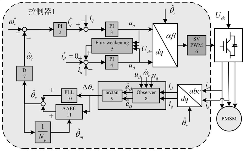
[0033] figure 1 A schematic structural diagram of a permanent magnet synchronous motor angle identification system of the present application is shown.

[0034] refer to figure 1 , in an embodimen...


PUM


Abstract

The invention discloses a permanent magnet synchronous motor angle identification system and method. The system comprises: a phase-locked loop used for calculating an aperiodic DC component of an angle; a self-adaptive angle compensator used for combining the non-periodic direct current component of the angle with the error angle to calculate and obtain an estimated electrical angle; a differentiator used for differentiating the estimated electrical angle to obtain an estimated rotating speed; an adaptive controller used for obtaining a trigonometric function coefficient of the initial periodic angle so as to obtain an estimated periodic angle; and an integrator used for obtaining a target trigonometric function coefficient so as to obtain a target periodic angle. According to the self-adaptive control principle, the trigonometric function coefficient of the periodic angle is identified in real time, and then the periodic angle is formed through combination; and in the control process, the periodic angle and the angle obtained through calculation of the phase-locked loop are added, the observation angle precision of position sensorless control is improved, the control performance can be greatly improved, and speed and current fluctuation is reduced.

Description

technical field [0001] The present invention relates to the technical field of motor control, and more specifically, to a permanent magnet synchronous motor angle identification system and method. Background technique [0002] Electrical Machine (Electrical Machine) is essentially an energy conversion device (interchange of electrical energy and mechanical energy). Torque rotation is generated through the magnetic field coupling between the stator and rotor. The magnetic field of the stator part is generated by current, and the magnetic field of the rotor part can be passed by current or permanent magnet. produce. The rotor part of the permanent magnet synchronous motor uses permanent magnets to form a magnetic field without additional current, so the motor has less loss and higher power density. It is precisely because of the advantages of high efficiency and energy saving that permanent magnet synchronous motors can be widely used in household products, especially in vari...

Claims


Application Information

Patent Timeline
IPC IPC(8): H02P21/18H02P25/022H02P27/12H02P6/182
CPCH02P21/18H02P25/022H02P27/12H02P6/182H02P2203/03H02P2207/05
Inventor 郝正强杨阳龚依民车晓镭张剑楠张晨晨宋红达郝正杰
Owner JILIN UNIV
Why Eureka
Try Eureka