Equipment and method for recovering volatile organic compounds

A volatile organic compound and equipment technology, applied in the field of volatile organic compound recovery equipment, can solve the problems of low saturation rate of spherical activated carbon, increase recovery cost, and inability to adsorb toluene, achieve high-efficiency adsorption, reduce recovery cost, and ensure adsorption efficiency. Effect

Inactive Publication Date: 2021-11-16
胡海波
View PDF1 Cites 0 Cited by
  • Summary
  • Abstract
  • Description
  • Claims
  • Application Information

AI Technical Summary

Problems solved by technology

[0004] However, in the actual use process, the researchers collected and tested the exhaust gas that needs to be discharged into the atmosphere, and found that the remaining amount of toluene in the exhaust gas accounted for about 12% of the total toluene in the exhaust gas. The actual purification efficiency is about 88%. In order to understand the specific reasons for the above situation, the researchers tested the saturation of the spherical activated carbon separated by the primary cyclone separator, and then learned that in this batch of spherical activated carbon, more than 32% of the spherical activated carbon

Method used


Image

  • Equipment and method for recovering volatile organic compounds
  • Equipment and method for recovering volatile organic compounds
  • Equipment and method for recovering volatile organic compounds

Examples


Embodiment 1

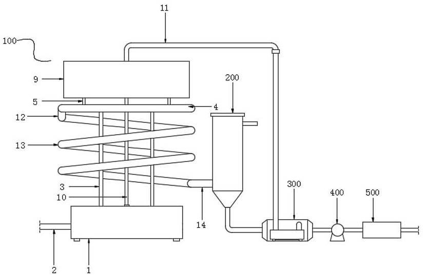
[0034] The present invention provides such as Figure 1-5 A device for recovering volatile organic compounds is shown, comprising an adsorption assembly 100, a cyclone separator 200, a desorber 300, an induced draft fan 400 and a condenser 500, the adsorption assembly 100, a cyclone separator 200, a desorber 300, an induction The fan 400 and the condenser 500 are communicated in sequence, and the desorber 300 is communicated with the adsorption assembly 100 through the adsorbent return mechanism 11 in the adsorption assembly 100. The adsorption assembly 100 includes a first sealed box 1, an L-shaped shunt pipe 3, and an annular junction Pipe 4, adsorbent feeding pipe 5, hopper 6 and a plurality of spherical activated carbon 7.

[0035] More specifically, the left side of the first sealed box 1 is fixedly provided with an exhaust gas input pipe 2, and a plurality of L-shaped shunt pipes 3, adsorbent feeding pipe 5 and hopper 6 are provided, and a plurality of L-shaped shunt pip...

Embodiment 2

[0047] The difference from the above-mentioned embodiment is that, if Figure 6 and Figure 7 As shown, since the plurality of spherical activated carbons 7 inside the hopper 6 are prone to jamming during the feeding process, in order to avoid the above problems:

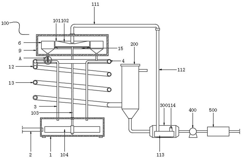
[0048] Two-way vibrating mechanism 15 is arranged between the bottom of bulk material pan 101 and multiple hoppers 6 insides, and bidirectional vibrating mechanism 15 comprises upper vibrating ring 151, lower vibrating ring 152, a plurality of semicircular cylinders 153 and a plurality of hemispherical extruders. The pressing block 154, the upper vibrating ring 151 are fixedly arranged on the inner bottom of multiple hoppers 6, the lower vibrating ring 152 is fixedly arranged on the bottom of the bulk material tray 101, and the lower vibrating ring 152 is located directly above the upper vibrating ring 151, and the plurality of semicircular columns The body 153 is evenly and fixedly arranged on the top of the upper...

Embodiment 3

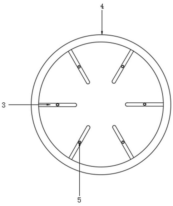
[0051] The difference from the above-mentioned embodiment is that, if figure 2 and Figure 5 As shown, after the recovered spherical activated carbon 7 falls into the screw feeding pipe 112, in order to make the spherical activated carbon 7 enter into a plurality of hoppers 6 from the screw feeding pipe 112 more conveniently, avoid the The situation that the spherical activated carbon 7 in a certain hopper 6 is used up, and the air flow inside the L-shaped shunt pipe 3 connected to the adsorbent feeding pipe 5 at the bottom runs empty:

[0052] In the present invention, a plurality of hoppers 6 are distributed in a ring shape, and the rotating impeller 104 is used to drive the bulk material disc 101 to rotate synchronously through the drive rod 103, so that the spherical activated carbon 7 falling into the conical groove 102 is driven by the bulk material disc. The centrifugal force generated when 101 rotates is evenly thrown into multiple hoppers 6, thereby avoiding the occ...


PUM


Abstract

The invention discloses equipment and a method for recovering volatile organic compounds, and relates to the technical field of volatile organic compound treatment. The equipment comprises an adsorption assembly, a cyclone separator, a desorber, an induced draft fan and a condenser. The adsorption assembly, the cyclone separator, the desorber, the induced draft fan and the condenser are communicated in sequence, the desorber is communicated with the adsorption assembly through an adsorbent feedback mechanism in the adsorption assembly, and the adsorption assembly comprises a first sealing box body, an L-shaped shunt pipe, an annular confluence pipe, an adsorbent blanking pipe, a hopper and a plurality of spherical activated carbon; a waste gas input pipe fixedly penetrates through the left side of the first sealing box body. Any spherical activated carbon can be in effective contact with methylbenzene evenly distributed in waste gas, then efficient adsorption of methylbenzene is achieved, a method for increasing the usage amount of the spherical activated carbon does not need to be adopted, and the recovery cost is effectively reduced while the adsorption efficiency is guaranteed.

Description

technical field [0001] The invention relates to the technical field of volatile organic compounds treatment, in particular to a device and method for recovering volatile organic compounds. Background technique [0002] Volatile organic compounds (VOCs) are relatively common and ubiquitous air pollutants in the atmosphere. Common components include hydrocarbons, benzene series, alcohols, ketones, phenols, esters, and amines. The sources are very extensive, not only industrial stationary sources such as petrochemicals, paint coatings, and leather production, but also mobile sources such as motor vehicle exhaust gases. Among them, the more common VOCs are toluene present in industrial exhaust gases. [0003] The invention patent of patent application publication number CN 110898614 A discloses a kind of equipment and method for recovering volatile organic compounds, wherein the equipment for recovering volatile organic compounds includes a circulating fluidized bed, a primary c...

Claims


Application Information

Patent Timeline
IPC IPC(8): B01D53/06B01D45/12
CPCB01D53/06B01D45/12B01D2253/102B01D2257/7027B01D2259/40088
Inventor 胡海波
Owner 胡海波
Why Eureka
Try Eureka