

Organic waste gas treatment system and treatment process
A technology of organic waste gas and treatment system, which is applied in gas treatment, combustion methods, lighting and heating equipment, etc., can solve the problems of increasing the operating burden of enterprises, consuming a lot of capacity, and spending a lot of energy, so as to save fresh air power and prolong use. Long life and small footprint
- Summary
- Abstract
- Description
- Claims
- Application Information
AI Technical Summary
Problems solved by technology
Method used
Image

Examples
Embodiment Construction
[0049] The present invention will be further described below in conjunction with the accompanying drawings and specific embodiments.
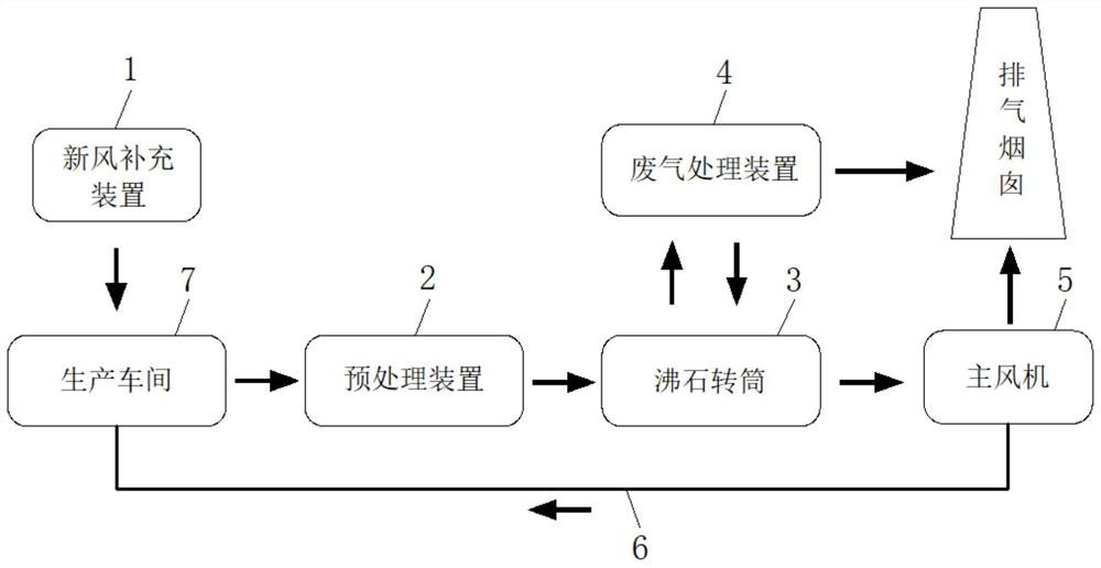
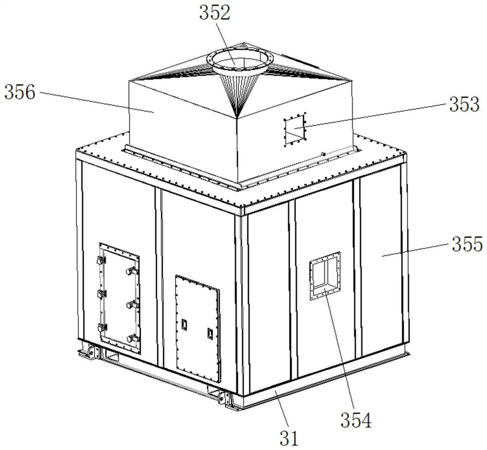
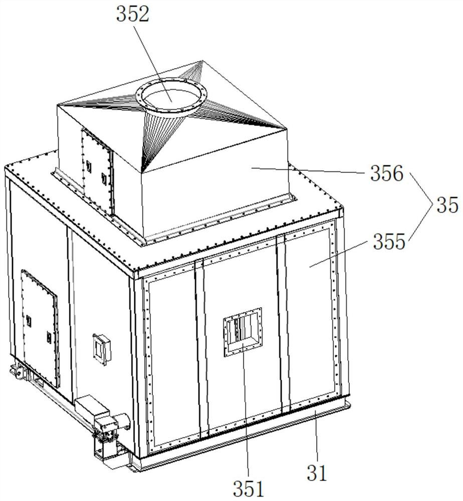
[0050] Such as Figure 1-18 As shown, an organic waste gas treatment system includes a fresh air replenishment device 1 , a pretreatment device 2 , a zeolite drum 3 , a waste gas treatment device 4 , a main fan 5 and a recycling pipeline 6 . The fresh air replenishment device 1 is connected to the production workshop 7 , and the air inlet end of the pretreatment device 2 is connected to the waste gas discharge port of the production workshop 7 . The pretreatment device 2 is one or more combinations of washing tower, dry filter, activated carbon adsorption unit, bag filter, cartridge filter, and electrostatic precipitator. The zeolite drum 3 includes a base 31, a gear transmission assembly 32 fixed on the base 31, a drum 33 mounted above the base 31 and driven to rotate by the gear transmission assembly 32, a desorption system fixed on the side...
PUM
 Abstract
Description
Claims
Application Information