Eureka AIR delivers breakthrough ideas for toughest innovation challenges, trusted by R&D personnel around the world.

New energy motor outer shell tail heat dissipation hole forming device

A technology for motor casings and forming devices, which is applied in the direction of feeding devices, positioning devices, storage devices, etc., can solve the problems of easy safety accidents and low efficiency, and achieve the effect of reducing labor intensity and improving work efficiency

Inactive Publication Date: 2021-11-16
黄梓玲
View PDF0 Cites 1 Cited by
  • Summary
  • Abstract
  • Description
  • Claims
  • Application Information

AI Technical Summary

Problems solved by technology

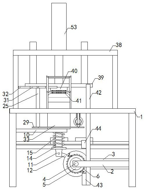
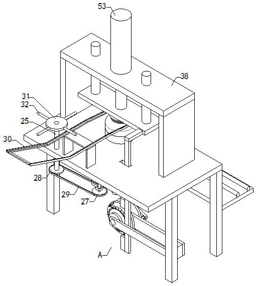
[0003] Some generator casings have cooling holes at the end to improve the heat dissipation performance of the generator and reduce the entry of impurities. In the prior art, the feeding and discharging of the casing are manually operated. This method is not efficient and is prone to safety accidents

Method used


Image

  • New energy motor outer shell tail heat dissipation hole forming device
  • New energy motor outer shell tail heat dissipation hole forming device
  • New energy motor outer shell tail heat dissipation hole forming device

Examples


Embodiment Construction

[0034] The specific implementation manners of the present invention will be further described in detail below in conjunction with the accompanying drawings and embodiments. The following examples are used to illustrate the present invention, but are not intended to limit the scope of the present invention.

[0035] In the description of the present invention, it should be noted that unless otherwise specified and limited, the terms "installation" and "connection" should be understood in a broad sense, for example, it can be a fixed connection, a detachable connection, or an integral Ground connection; it can be a mechanical connection or an electrical connection; it can be a direct connection or an indirect connection through an intermediary, and it can be the internal communication of two components. Those of ordinary skill in the art can understand the specific meanings of the above terms in the present invention in specific situations.

[0036] like Figure 1 to Figure 10...


PUM


Abstract

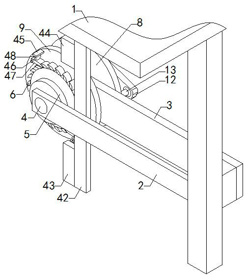
The invention relates to the technical field of motor accessory devices, and particularly relates to a new energy motor outer shell tail heat dissipation hole forming device. The device is simple in structure and capable of automatically feeding and discharging outer shells, improving the automation degree, improving the machining efficiency and reducing the labor intensity of operators. The device comprises a supporting table serving as a base body of the whole device, a forming mechanism, a discharging mechanism and a feeding mechanism are arranged on the supporting table, and supporting legs are arranged at the four corners of the bottom of the supporting table; the forming mechanism is used for forming the motor outer shells; the discharging mechanism is installed on one side of the forming mechanism, driven by the forming mechanism and used for pushing the motor outer shells to ascend and incline, and discharging is completed; and the feeding mechanism is installed on the other side of the forming mechanism, driven by the forming mechanism and used for feeding materials to the forming mechanism.

Description

technical field [0001] The invention relates to the technical field of motor attachments, in particular to a cooling hole forming device at the rear of a new energy motor housing. Background technique [0002] The generator is composed of stator, rotor, end cover, machine base and bearings, etc. The stator is composed of machine base, stator core, wire wrap winding, and other structural parts that fix these parts. The rotor is composed of rotor core (with magnetic yoke, magnetic pole winding), slip ring, (also known as collector ring), fan and shaft and other components. The stator and rotor of the generator are connected and assembled by the bearing and the end cover, so that the rotor can rotate in the stator and do the movement of cutting the magnetic induction line, thereby generating an induced potential, which is drawn out through the terminal and connected to the circuit, thus generating current. [0003] Some generator casings have cooling holes at the rear to impr...

Claims


Application Information

Patent Timeline
Patent Type & Authority Applications(China)
IPC IPC(8): B21D28/24B21D43/02B21D43/20
CPCB21D28/24B21D43/02B21D43/20
Inventor 黄梓玲
Owner 黄梓玲
Why Eureka
Eureka Blog
Learn More