Multi-row multi-shaft furniture wood drilling machine

A furniture woodworking and drilling machine technology, applied in the field of multi-row and multi-axis furniture woodworking drilling machines, can solve problems such as damage to the surface of the board, reduced performance, no safety protection, etc., and achieves improved performance, reduced friction, and is not easy to scratch Effect

Inactive Publication Date: 2021-11-16
曾欣宇
View PDF7 Cites 0 Cited by
  • Summary
  • Abstract
  • Description
  • Claims
  • Application Information

AI Technical Summary

Problems solved by technology

[0005] Aiming at the deficiencies of the prior art, the present invention provides a multi-row and multi-axis furniture woodworking drilling machine, which solves the problem of inconvenient unloading after processing some large and heavy boards when the existing furniture boards are drilled, and there is no broken material. Chip self-cleaning function, debris will adhere to the surface of the plate, when unloading, there will be a large friction between the plate and the workbench, prone to scratches, without safety protection, the surface of the plate will be damaged, in severe cases Cause the plate to be scrapped and reduce the performance

Method used


Image

  • Multi-row multi-shaft furniture wood drilling machine
  • Multi-row multi-shaft furniture wood drilling machine
  • Multi-row multi-shaft furniture wood drilling machine

Examples


Embodiment example 1

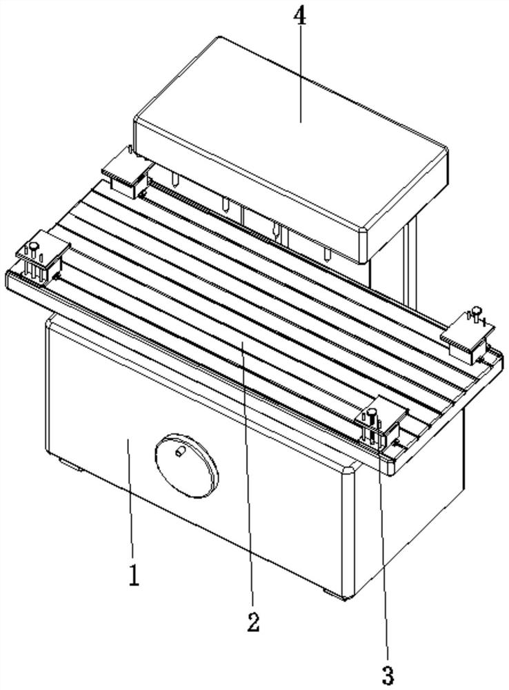
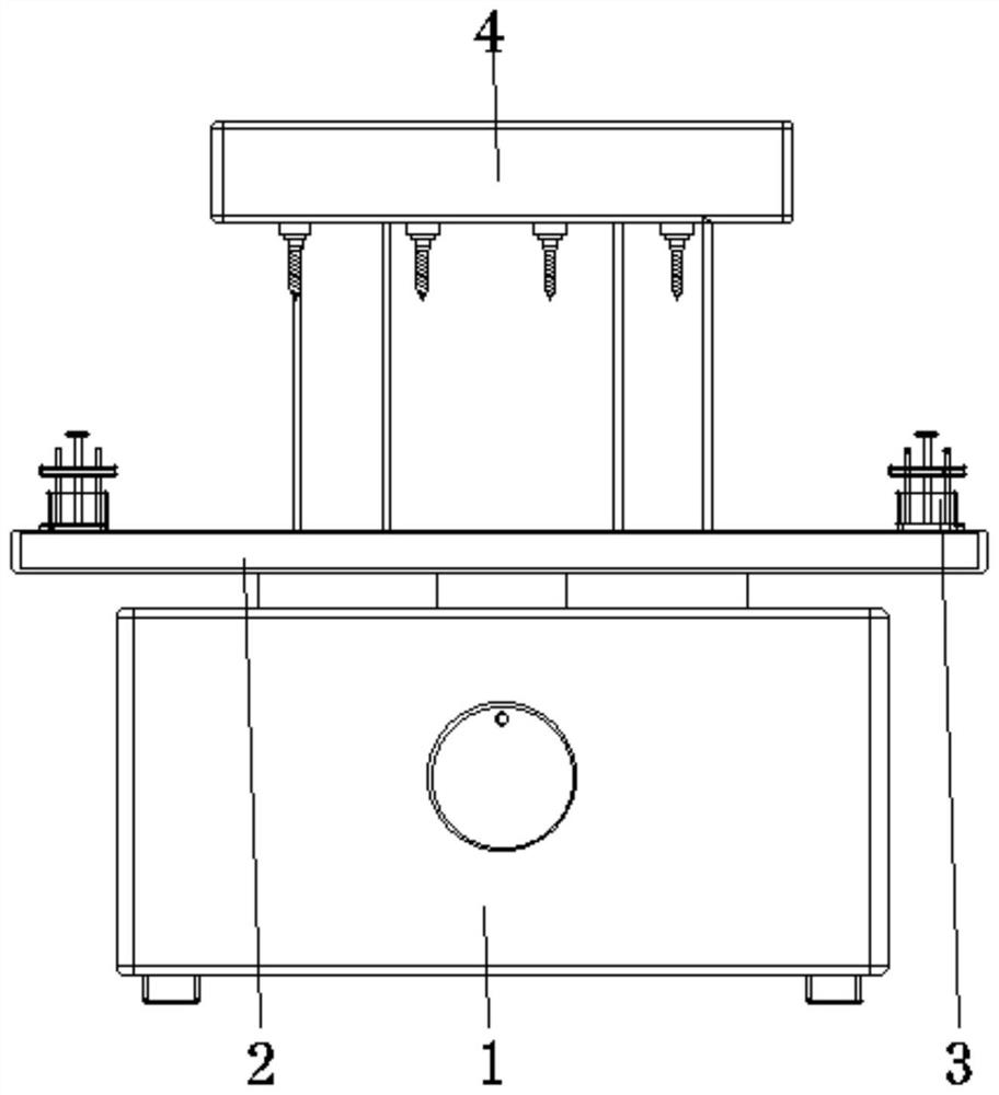
[0031] see Figure 1-7 , the present invention provides a technical solution: a multi-row multi-axis furniture woodworking drilling machine, including a body 1, a workbench 2, a clamping device 3, a multi-row multi-axis drilling mechanism 4, and the workbench 2 is arranged on the top of the body 1 , the clamping device 3 is arranged at a position corresponding to the top of the workbench 2, and the multi-row multi-axis drilling mechanism 4 is arranged on the top side of the surface of the body 1 and is located at the top of the workbench 2;

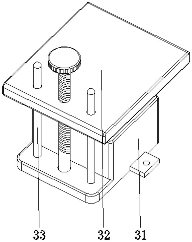
[0032] The clamping device 3 is provided with a supporting device 31, a pressing device 32, and a guide rod 33. The bottom of the supporting device 31 is fixedly connected with the top of the workbench 2, and the pressing device 32 is connected with the supporting device 31. The bottom end is fixedly connected to the bottom side of the surface of the support device 31, and the surface of the guide rod 33 is connected with the pressing dev...

Embodiment example 2

[0034]The support device 31 is provided with a base 311, a bracket slide plate 312, a support spring 313, a rolling device 314, and an air outlet device 315. The bottom of the base 311 is fixedly connected to the top of the workbench 2, and the support slide plate 312 is slidably connected to the base 311 inside and close to the top position, the support spring 313 is fixed between the top of the inner wall of the bracket slide plate 312 and the corresponding two sides inside the base 311, the rolling device 314 is arranged inside the base 311 and is located at the top position, the rolling device 314 The end part is connected with the bracket slide plate 312, and the air outlet device 315 is arranged inside the base 311 and directly below the rolling device 314. When the plate needs to be clamped, the plate is placed on the supporting device 31, and the plate is The rolling device 314 is pressed down by its own weight, and supported by the base 311, and the plate is clamped by...

Embodiment example 3

[0036] Compression device 32 is provided with threaded rod 321, pressing plate 322, anti-skid pad 323, and the bottom of threaded rod 321 is connected with the surface bottom edge of support device 31 in rotation, between pressing plate 322 and the surface of threaded rod 321, threaded connection, anti-slip pad 323 Fixed on the bottom of the pressure plate 322, the threaded rod 321 can be turned in time to drive the pressure plate 322 to move up and down, thereby realizing the loosening and clamping of the plate, and the guide rod 33 is used to make the whole structure more stable. And the downward pressure of the pressing plate 322 is applied to the supporting device 31, further making the plate placed smoothly without moving or shaking, and the combination of structures is used to improve the support and clamping of the plate, which is helpful for fast drilling.


PUM


Abstract

The invention discloses a multi-row multi-shaft furniture wood drilling machine which comprises a machine body, a workbench, a clamping device and a multi-row multi-shaft drilling mechanism, the workbench is arranged at the top of the machine body, and the clamping device is arranged at the corresponding position of the top of the workbench; the multi-row multi-shaft drilling mechanism is arranged on one side of the top of the surface of the machine body and located at the top of the workbench, the bottom of a supporting device is fixedly connected with the top of the workbench, a pressing device is connected with the supporting device in a matched mode, and the bottom end of a guide rod is fixedly connected with one side of the bottom of the surface of the supporting device; and the surface of the guide rod is connected with the pressing device in a matched mode. The invention relates to the technical field of furniture drilling equipment. According to the multi-row multi-shaft furniture wood drilling machine, the purpose of rapid discharging is achieved, friction between plates and the workbench is reduced, discharging is rapid and convenient, time and labor are saved, scratches are not prone to occurring, the working efficiency is high, and the working efficiency and the using performance are improved.

Description

technical field [0001] The invention relates to the technical field of furniture drilling equipment, in particular to a multi-row multi-axis furniture woodworking drilling machine. Background technique [0002] Furniture is an indispensable item in people's daily life, and furniture is designed through various panels. In the process of furniture processing, the furniture board needs to be drilled through a drilling process for subsequent installation. Drilling machine refers to a machine tool that mainly uses a drill bit to process holes on a workpiece. Usually, the rotation of the drill bit is the main movement, and the axial movement of the drill bit is the feed movement. The drilling machine has a simple structure and relatively low machining accuracy. It can drill through holes and blind holes, and replace special tools. , can be reamed, countersinked, reamed, or tapped. During the processing, the workpiece does not move, the tool moves, the center of the tool is aligne...

Claims


Application Information

Patent Timeline
IPC IPC(8): B27C3/04B27M3/18B27G3/00
CPCB27C3/04B27M3/18B27G3/00
Inventor 曾欣宇
Owner 曾欣宇
Why Eureka
Try Eureka