A precise detection method for geological structures based on directional-while-drilling phase change vector seismic measurement

A technology of geological structures and detection methods, applied in seismology, measurement devices, seismic signal processing, etc., can solve problems such as difficulty in identifying geological structures, limitations on the accuracy of 3D seismic exploration, and difficulty in accurate detection.

Active Publication Date: 2022-05-17
CHINA UNIV OF MINING & TECH
View PDF11 Cites 0 Cited by
  • Summary
  • Abstract
  • Description
  • Claims
  • Application Information

AI Technical Summary

Problems solved by technology

[0002] At present, 3D seismic technology is commonly used in the detection of geological structures. However, due to the influence of unfavorable factors such as complex terrain, loess coverage, exposed bedrock, and surface water bodies, the accuracy of 3D seismic exploration is limited. 3D seismic results can delineate geological structure areas, but it is difficult to accurately detect them.
Compared with the 3D seismic method, drilling is the most direct method, but it has the limitation of seeing one hole at a time. In areas with complex geological structures, it is very difficult to distinguish geological structures due to the difficulty of coring
In order to solve this problem, logging technology has been developed, but it is limited by objective conditions such as method and power. Logging technology can only identify the lithology of the borehole and the geological structure at a very short distance around the borehole, and it is difficult to identify the long-distance Geological structure

Method used


Image

  • A precise detection method for geological structures based on directional-while-drilling phase change vector seismic measurement
  • A precise detection method for geological structures based on directional-while-drilling phase change vector seismic measurement

Examples


Embodiment Construction

[0030] The present invention will be further described below.

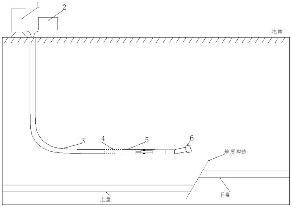
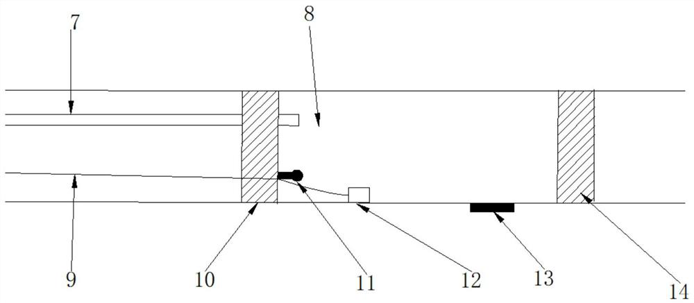
[0031] Such as figure 1 with figure 2 Shown, with the drilling direction of directional drill bit as the front is described, and concrete steps of the present invention are:

[0032] Step 1. Preliminary delineation of the detection area: use geophysical detection methods on the ground to find out the general distribution of underground geological structures, and delineate multiple target areas of geological structures to be accurately detected;

[0033] Step 2, assemble the directional detection equipment: connect the front end of the non-magnetic drill rod 5 with the directional drill bit 6, connect the rear end of the conventional drill rod 3 with the drilling machine, and install a phase change vector between the conventional drill rod 3 and the non-magnetic drill rod 5 The seismic device 4, the front end of the phase change vector seismic device 4 is coaxially connected with the rear end of the non-magnetic...


PUM


Abstract

The invention discloses a precise geological structure detection method based on directional-while-drilling phase-change vector seismic measurement. Firstly, a plurality of geological structure target areas are determined, and then the phase-change vector seismic measurement device reaches the first geological structure target through directional drilling. area, first inject liquid CO into the storage chamber 2 And heating the phase change gasification pressurization, through the opening and closing of the electronically controlled valve, the high-pressure gas shocks the formation directly opposite the ejection hole to generate seismic waves; then the vector collector transmits the collected diffraction wave signals to the control center, and through the positioning algorithm Analysis and processing are carried out to complete the precise detection of the geological structure in the lower area; then the phase-change vector seismic device is rotated at multiple angles, and multiple gas shocks and signal processing processes are performed to finally complete the 360° full-scale survey of the geological structure target area. Accurate detection of azimuth; repeating the above process many times, can complete 360° all-round accurate detection of all geological structure target areas. Therefore, it can not only carry out large-scale and all-round geological structure detection, but also effectively ensure the detection accuracy.

Description

technical field [0001] The invention relates to a precise detection method of geological structure, in particular to a precise detection method of geological structure based on directional-while-drilling phase change vector seismic measurement. Background technique [0002] At present, 3D seismic technology is commonly used in the detection of geological structures. However, due to the influence of unfavorable factors such as complex terrain, loess coverage, exposed bedrock, and surface water bodies, the accuracy of 3D seismic exploration is limited. 3D seismic results can delineate geological structure areas, but it is difficult to accurately detect them. . Compared with the 3D seismic method, drilling is the most direct method, but it has the limitation of seeing one hole at a time. In areas with complex geological structures, it is very difficult to distinguish geological structures due to the difficulty of coring. In order to solve this problem, logging technology has b...

Claims


Application Information

Patent Timeline
Patent Type & Authority Patents(China)
IPC IPC(8): G01V1/00G01V1/133G01V1/20G01V1/30
CPCG01V1/00G01V1/133G01V1/20G01V1/306Y02A90/30
Inventor 王勃李晓昭周官群李福清王刚胡思源吕宪状王一帆陈泓云
Owner CHINA UNIV OF MINING & TECH
Why Eureka
Try Eureka