
Pre-assembled piston accumulator device

A technology of accumulator and piston, applied in the direction of control device, auxiliary drive device, shock absorber, etc., can solve the problems of increasing the size and cost of damper

Active Publication Date: 2021-11-16
TENNECO AUTOMOTIVE OPERATING CO INC
View PDF8 Cites 0 Cited by
  • Summary
  • Abstract
  • Description
  • Claims
  • Application Information

AI Technical Summary

Problems solved by technology

Current dampers also have check valves that further increase the size and cost of the damper

Method used


Image

  • Pre-assembled piston accumulator device
  • Pre-assembled piston accumulator device
  • Pre-assembled piston accumulator device

Examples


Embodiment Construction

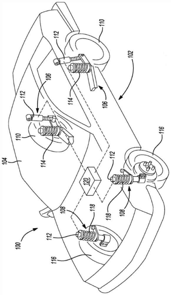
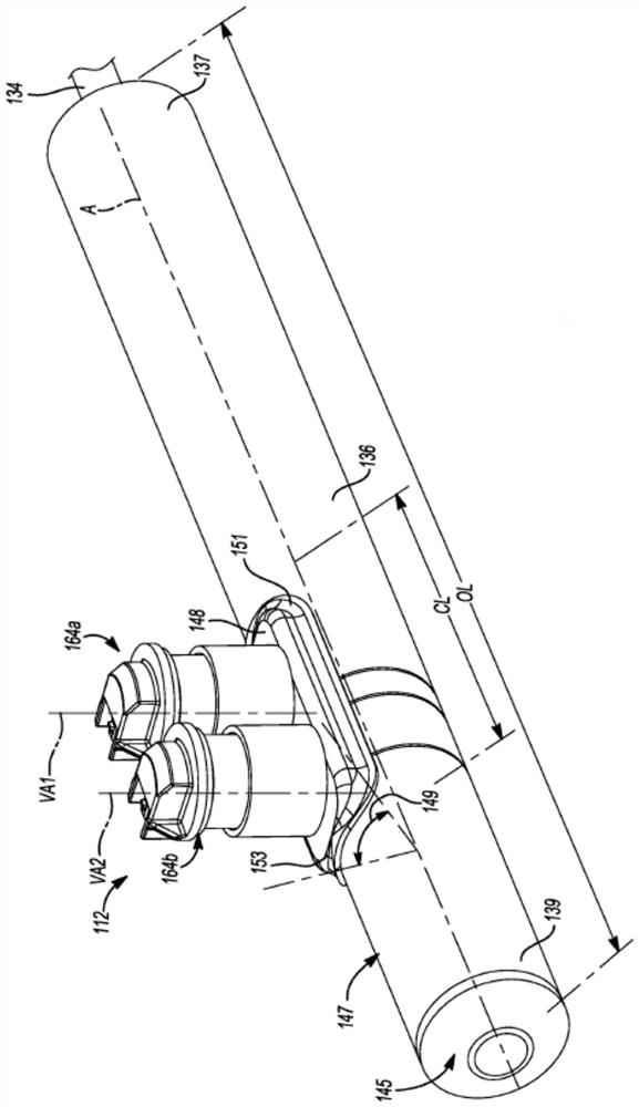
[0024] Exemplary embodiments will now be described more fully with reference to the accompanying drawings. Wherever possible, the same reference numbers will be used throughout the drawings to refer to the same or like parts.

[0025] Exemplary embodiments will now be described more fully with reference to the accompanying drawings. Example embodiments are provided so that this disclosure will be thorough, and will fully convey the scope to those who are skilled in the art. Numerous specific details are set forth, such as examples of specific components, devices and methods, to provide a thorough understanding of embodiments of the present disclosure. It will be apparent to those skilled in the art that specific details need not be employed, that example embodiments may be embodied in many different forms and that neither should be construed to limit the scope of the disclosure. In some example embodiments, well-known processes, well-known device structures, and well-known t...


PUM


Abstract

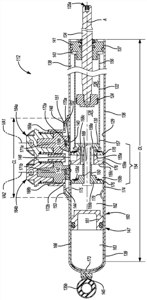
A damper with inner and outer tubes and a piston disposed within the inner tube to define first and second working chambers is disclosed. A fluid transport chamber is positioned between the inner and outer tubes. A collector chamber is positioned outside the outer tube. An intake valve assembly, abutting one end of the inner tube, is positioned inside the outer tube. An accumulator insert with an open end abutting the intake valve assembly is positioned inside the outer tube. The accumulator insert includes an accumulator sleeve, a floating piston, and a pressurized chamber. The floating piston is disposed inside the accumulator sleeve and the pressurized chamber is positioned between the floating piston and a closed end of the accumulator sleeve. An accumulation chamber is positioned between the intake valve assembly and the floating piston and the accumulator sleeve includes one or more apertures arranged in fluid communication with the collector chamber.

Description

technical field [0001] The present disclosure generally relates to dampers. More specifically, the present disclosure relates to a damper having a floating piston accumulator mounted to a side collector and a plurality of external control valves. Background technique [0002] This section provides background information related to the present disclosure which is not necessarily prior art. [0003] Vehicles often include dampers used in conjunction with the suspension system to absorb vibrations that occur when the vehicle is driven. To absorb vibrations, dampers are usually attached between the vehicle's body and suspension system. The piston is located inside the damper. The piston is connected to the body or vehicle suspension by a piston rod. The damper also includes a damper body that is connected to the suspension system. When the damper is compressed or extended, the piston may restrict the flow of damping fluid between a first working chamber and a second working...

Claims


Application Information

Patent Timeline
IPC IPC(8): F16F9/02F16F9/34F16F9/36B60G13/14
CPCF16F9/02F16F9/34F16F9/36B60G13/14F16F9/185F16F9/3271F16F9/3257F16F9/325F16F9/3214
Inventor S·德雷姆
Owner TENNECO AUTOMOTIVE OPERATING CO INC
Learn More