Eureka AIR delivers breakthrough ideas for toughest innovation challenges, trusted by R&D personnel around the world.

Modular external ac charger

A charging device and basic module technology, applied in the direction of circuit devices, battery circuit devices, charging stations, etc., can solve the problems that the charging device requires structural space, increase the total weight of the vehicle, etc., and achieve the effect of reducing additional weight and high flexibility

Pending Publication Date: 2021-11-19
AUDI AG
View PDF10 Cites 0 Cited by
  • Summary
  • Abstract
  • Description
  • Claims
  • Application Information

AI Technical Summary

Problems solved by technology

The installed charging device requires construction space and increases the overall weight of the vehicle and its manufacturing costs

Method used


Image

  • Modular external ac charger
  • Modular external ac charger
  • Modular external ac charger

Examples


Embodiment Construction

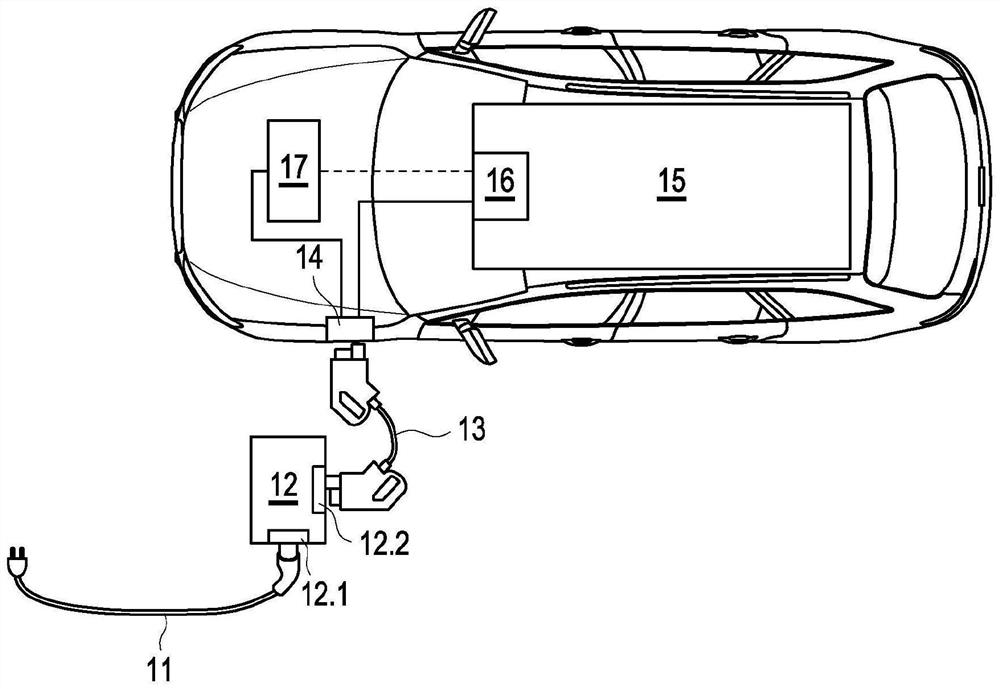
[0032]FIG. 1 shows a schematic diagram of an electric or hybrid vehicle with a charging device 12 according to the prior art.

[0033] The AC current input terminal 12.1 of the charging device 12 is connected to an AC power source, such as a power grid, through an AC cable 11 with an In-Cable Control and Protechnological Device (IC-CPD). The charging device includes a rectifier (AC / DC converter). The DC current output 12 . 2 of the charging device 12 is connected via a DC cable 13 to a charging socket 14 (CCS) of the vehicle. The direct current is transmitted to the high-voltage battery 15 of the vehicle via a switching unit 16 ("Battery Junction Box", BJB) of the battery management system. The charging process is regulated by the vehicle's control device 17 (Electronic Control Unit, ECU). The power components of the charging device 12 that perform the voltage conversion (AC / DC) are therefore located outside the vehicle.

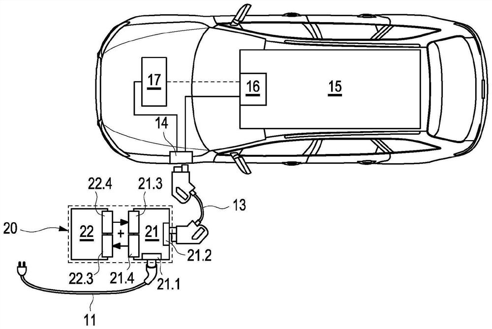
[0034] figure 2 An electric or hybrid vehicle with...


PUM


Abstract

Movable modular external AC charger and AC charging system for high-voltage batteries of electric or hybrid motor vehicles. A portable modular external AC charger and an AC charging system for a high-voltage battery of an electric or hybrid motor vehicle, may allow charging performance and range of functions to be adapted as desired.

Description

technical field [0001] The invention relates to a mobile, modular external AC charging device and an AC charging system for high-voltage batteries of electric or hybrid vehicles, wherein the charging power and functional range can be adapted as desired. Background technique [0002] Current electric vehicles and hybrid vehicles have a charging device permanently installed in the vehicle, the so-called on-board charger (OBC), in order to charge their high-voltage battery with alternating current. The connection cable is used to connect and communicate with the loaded charging device and an AC power source, such as a socket or an AC charging pile (AC charging pile). The installed charging device requires installation space and increases the overall weight of the vehicle and its production costs. Furthermore, the installed charging device has a fixed maximum charging power and a range of functions depending on the hardware used. Therefore, it has been proposed to replace the ...

Claims


Application Information

Patent Timeline
Patent Type & Authority Applications(China)
IPC IPC(8): B60L53/30B60L53/53
CPCB60L53/30B60L53/53Y02T10/70Y02T10/7072Y02T90/12B60L53/14B60L53/11B60L2210/30H02J7/0042H02J2207/40H02J2207/20H02J7/342Y02T10/72Y02T90/14H02J7/04H02J7/00032H02J7/0045
Inventor S·基施纳
Owner AUDI AG
Why Eureka
Eureka Blog
Learn More