Double-layer and double-effect heat insulation wall for afterburner cavity and double-effect cooling method

A technology of afterburner and heat insulation wall, applied in the combustion method, combustion chamber, continuous combustion chamber and other directions, can solve the problems of reducing the temperature of supersonic aircraft engine, improve the utilization rate of cold air, strengthen convective heat transfer, improve The effect of longevity and reliability

Active Publication Date: 2021-11-19
NORTHWESTERN POLYTECHNICAL UNIV
View PDF11 Cites 2 Cited by
  • Summary
  • Abstract
  • Description
  • Claims
  • Application Information

AI Technical Summary

Problems solved by technology

In addition, as the air flow required for mainstream combustion increases, the air flow used for cooling decreases. Therefore, a heat shield structure with efficient cooling capabilities for supersonic aircraft engines must be applied, that is, with as little cold air as possible The air achieves a better cooling effect, and the maximum limit reduces the temperature of the supersonic aircraft engine

Method used


Image

  • Double-layer and double-effect heat insulation wall for afterburner cavity and double-effect cooling method
  • Double-layer and double-effect heat insulation wall for afterburner cavity and double-effect cooling method
  • Double-layer and double-effect heat insulation wall for afterburner cavity and double-effect cooling method

Examples


Embodiment 1

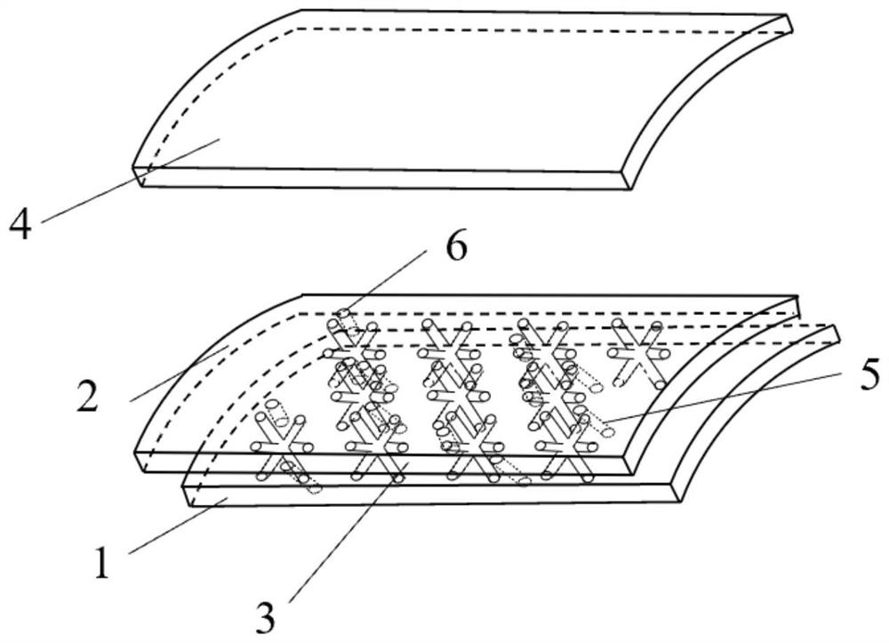
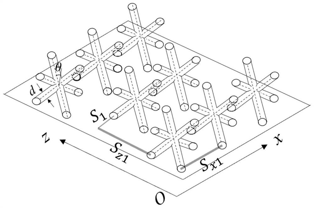
[0030] Embodiment 1: as Figure 1-Figure 3 As shown, a double-layer double-effect heat-insulating wall for the cavity of the afterburner, the inner wall of the afterburner includes an air film orifice plate 1 and an impact orifice plate 2, and the air mold orifice plate 1 and the impact orifice plate There are a plurality of Mi-shaped trusses 3 arranged in a matrix in the cavity between 2. The Mi-shaped trusses 3 are composed of three truss rods. The midpoints of the three truss rods cross each other to form a central intersection point. They are respectively connected to the impact orifice plate 2 and the air film orifice layer 1; the ratio of the diameter d of the Pozirette truss 3 to the distance H between the impact orifice plate 2 and the air film orifice plate 1 ranges from 0.05 to 0.25. The wall normal angle between the rice word truss 3 and the air film orifice 1 is θ, and θ is 30-60°; The distance between plates 2, then l=H / cosθ.

[0031] The matrix arrangement of a...

Embodiment 2

[0039] Embodiment 2: as Figure 4 , Figure 5 As shown, the present invention also relates to a double-effect cooling method for a double-layer double-effect heat insulation wall of an afterburner cavity, comprising the following steps:

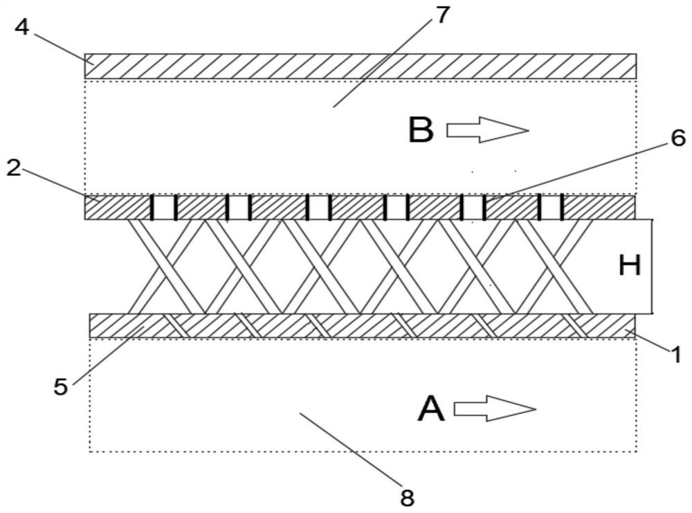
[0040] Such as Figure 4 As shown, the part of the cooling air flow B in the cold air duct 7 is perpendicular to the impingement jet C1 of the impingement orifice plate 2, and enters the air film orifice plate 1 and the impingement hole through the impingement hole 6 on the impingement orifice plate 2 the cavity between the plates 2;

[0041] The impact jet C1 that enters the cavity between the air film orifice plate 1 and the impact orifice plate 2 is a part of the impact jet that directly impacts and cools the inner wall of the air film orifice plate 1 to form an impact cooling air flow C3, and the other part impacts The Pozierdo truss 3 collides with the surface of the Pozieri truss 3 to form a flow around the Pozierian truss C2;

[00...


PUM


Abstract

The invention relates to a double-layer double-effect heat insulation wall for an afterburner cavity and a double-effect cooling method. The inner wall of the afterburner comprises a gas film pore plate and an impact pore plate, a plurality of *-shaped trusses are arranged in a cavity between the gas film pore plate and the impact pore plate in a matrix mode, each *-shaped truss is composed of three truss rods, midpoints of the three truss rods intersect with one another to form a central intersection point, and the two ends of the three truss rods are connected with the impact pore plate and the gas film pore layer respectively; gas film pores are formed in the gas film pore plate; and impact pores are formed in the impact pore plate. Two longitudinal rotating vortexes of the heat insulation wall in a convection channel accelerate heat exchange, the temperature between the impact pore plate and the gas film pore plate is fully reduced, the cooling pressure on the gas film pore plate is accelerated to be reduced, gas film covering is formed on the gas side of a heat insulation screen through the structure, direct contact between gas and an engine force bearing structure is blocked, the service life and the reliability of the afterburner are improved, and the double-layer double-effect heat insulation wall has good mechanical properties.

Description

technical field [0001] The invention belongs to the field of gas turbine engines, and in particular relates to a double-wall heat insulating wall structure and a cooling method of an afterburner. Background technique [0002] Supersonic aircraft engines usually have afterburners, and supersonic aircraft place great emphasis on the acceleration of the aircraft. The gas behind the engine turbine still contains a part of oxygen. The supersonic aircraft engine has an afterburner behind the turbine, which mixes the oxygen-containing gas with the fresh air in the external duct, and then injects fuel into it, and continues to burn after ignition. The high-temperature gas velocity at the outlet of the tail nozzle is increased, so that the thrust of the engine is further increased on the original basis. The afterburner is usually used in the take-off phase and the maneuvering flight phase that requires rapid acceleration. When the afterburner is turned on, the thrust can usually be ...

Claims


Application Information

Patent Timeline
Patent Type & Authority Applications(China)
IPC IPC(8): F23R3/00
CPCF23R3/002F23R2900/03045
Inventor 白晓辉刘存良刘海涌傅松王子文
Owner NORTHWESTERN POLYTECHNICAL UNIV
Why Eureka
Try Eureka