
Continuous detection equipment based on industrial flue gas

A technology for testing equipment and industrial flue gas, which is applied in the direction of measuring devices, sampling, instruments, etc., can solve problems such as inability to realize flue gas sampling, affect detection accuracy, and fail to achieve, achieve accurate sulfide content and dust particle concentration, and improve Detection accuracy, the effect of good detection accuracy

Active Publication Date: 2021-11-19
金广恒环保技术(南京)股份有限公司
View PDF12 Cites 2 Cited by
  • Summary
  • Abstract
  • Description
  • Claims
  • Application Information

AI Technical Summary

Problems solved by technology

[0009] Aiming at the deficiencies of the existing technology, the present invention provides a continuity detection device based on industrial flue gas, which solves the problem that the detection accuracy of the existing detection equipment is low, and the sampling is not flexible enough, and only a single collection of flue gas can be realized And detection, especially for some large-scale smoke emission detection occasions, the detection accuracy is very poor, for example, in some large thermal power plants or chemical plants, the smoke is exhausted through the top of the combustion tower, and one-way sampling is used, which seriously affects the detection accuracy. It cannot be realized that through flexible sampling of flue gas, the detection equipment can randomly select flue gas from different positions for inspection, and it is impossible to adjust the detection position according to the reagent detection requirements, so that the inspectors can conduct more accurate detection of smoke Questions for air sulfide content and dust particle concentration purposes

Method used


Image

  • Continuous detection equipment based on industrial flue gas
  • Continuous detection equipment based on industrial flue gas
  • Continuous detection equipment based on industrial flue gas

Examples


Embodiment Construction

[0041] The following will clearly and completely describe the technical solutions in the embodiments of the present invention with reference to the accompanying drawings in the embodiments of the present invention. Obviously, the described embodiments are only some, not all, embodiments of the present invention. Based on the embodiments of the present invention, all other embodiments obtained by persons of ordinary skill in the art without making creative efforts belong to the protection scope of the present invention.

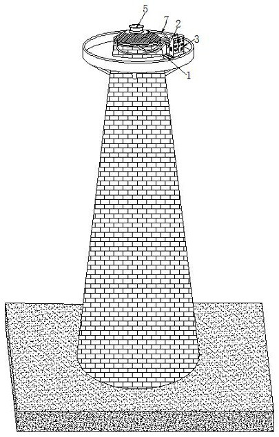
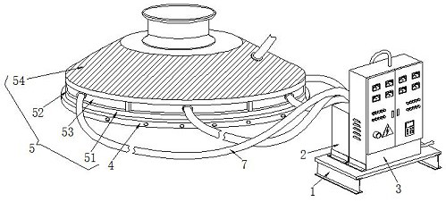
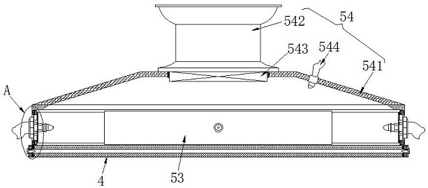
[0042] see Figure 1-11 , the embodiment of the present invention provides a technical solution: a continuity detection device based on industrial flue gas, including a mounting frame 1 fixedly installed on the top platform of the reaction tower and a control box fixedly installed on the top of the mounting frame 1 respectively through connectors 2 and the detection unit 3 also include an adjustable sampling mechanism 5 fixedly installed on the top of the reac...


PUM


Abstract

The invention discloses continuous detection equipment based on industrial flue gas. The equipment comprises a mounting frame fixedly mounted on a platform at the top of a reaction tower, wherein a control box and a detection unit which are fixedly mounted at the top of the mounting frame through connecting pieces, and an adjustable sampling mechanism fixedly mounted at the top of the reaction tower through a mounting assembly, and a continuous gas distribution mechanism is arranged in the control box. The invention relates to the technical field of flue gas treatment environmental protection equipment. According to the continuous detection equipment based on the industrial flue gas, the flue gas can be flexibly sampled, so the detection equipment can randomly extract the flue gas at different positions for detection, and the detection position can be well adjusted according to reagent detection requirements; therefore, detection personnel can more accurately detect the sulfide content and the dust particle concentration in the flue gas, sampling is flexible, and detection precision is greatly improved.

Description

technical field [0001] The invention relates to the technical field of flue gas treatment and environmental protection equipment, in particular to a continuity detection device based on industrial flue gas. Background technique [0002] Industrial flue gas contains sulfur and other harmful substances, which need to be purified and discharged, and a continuous monitoring device for flue gas emission is installed to measure the concentration of pollutants in the factory exhaust gas in real time, continuously or intermittently. Real-time continuous detection is usually directly in the flue gas The detection probe is installed in the exhaust pipe to realize the continuous monitoring of the flue gas emission. Due to the limited detection of the probe head and low detection accuracy, it is easy to be damaged and has a short service life when it is in direct contact with the flue gas at a high temperature for a long time in the exhaust pipe. The type measurement is to collect the f...

Claims


Application Information

Patent Timeline
Patent Type & Authority Applications(China)
IPC IPC(8): G01N33/00G01N15/06G01N1/24G08C17/02
CPCG01N33/0044G01N15/06G01N1/2258G01N1/2202G08C17/02
Inventor 于培勇
Owner 金广恒环保技术(南京)股份有限公司
Learn More