Check patentability & draft patents in minutes with Patsnap Eureka AI!

Speckle-based image distortion correction for laser scanning microscopy

A technology for scanning imaging equipment, images, applied in the direction of adopting optical devices, optics, applications, etc., to achieve cost-effective and robust results

Pending Publication Date: 2021-11-19
THE GENERAL HOSPITAL CORP
View PDF0 Cites 0 Cited by
  • Summary
  • Abstract
  • Description
  • Claims
  • Application Information

AI Technical Summary

Problems solved by technology

[0005] Image distortion caused by non-uniform laser scanning can pose a challenge for certain laser scanning imaging devices such as catheter endoscopes and capsule endoscopes

Method used


Image

  • Speckle-based image distortion correction for laser scanning microscopy
  • Speckle-based image distortion correction for laser scanning microscopy
  • Speckle-based image distortion correction for laser scanning microscopy

Examples


Embodiment Construction

[0029] According to some embodiments of the disclosed subject matter, mechanisms (which may include systems, methods, and media) for image distortion correction are provided.

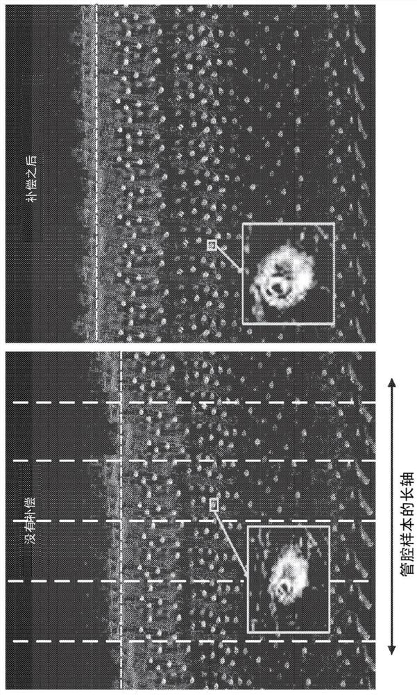
[0030] Laser speckle (which in some cases can be considered as unwanted artifacts) may be used to advantage various disclosed embodiments. In various embodiments, distorted features and features with specific local brightness, such as laser speckle, are used in the disclosed procedures to compensate and are readily identified using the automated procedures disclosed herein. Although these features are referred to in this paper as laser speckle, these features can have other origins as well, but are still useful for identifying and correcting image distortions.

[0031] In many imaging use environments (e.g., capsule endoscopy using illumination lasers), undesired distortion artifacts may arise. For example, in a 360° rotating capsule endoscope environment, the motors that rotate the illumination laser...


PUM

PropertyMeasurementUnit
sizeaaaaaaaaaa

Abstract

A method of correcting distortion of an image, including: analyzing, by a processor, an image segment of the image to identify a speckle artifact, the image segment being obtained from a scanning imaging device; determining, by the processor, an aspect ratio of a shape of the speckle artifact; determining, by the processor, a correction factor for the shape of the speckle artifact based on the aspect ratio; and adjusting, by the processor, a dimension of the image segment based on the correction factor.

Description

[0001] Cross References to Related Applications [0002] This application is based upon, claims the benefit of, and claims priority from U.S. Provisional Patent Application No. 62 / 797,548, filed January 28, 2019, which is hereby incorporated by reference in its entirety for all purposes. [0003] A Note About Federally Funded Research [0004] This invention was made with government support No. R01DK091923 awarded by the National Institutes of Health. The government has certain rights in this invention. Background technique [0005] Image distortion caused by non-uniform laser scanning can pose a challenge to certain laser scanning imaging devices such as catheter endoscopes and capsule endoscopes. For example, components associated with rotation or scanning may have a certain amount of friction, and this friction may vary during rotation, eg, depending on the orientation of the imaging device or the waveform of the scan. Since this friction is generally unknown and unpredi...

Claims


Application Information

Patent Timeline
Patent Type & Authority Applications(China)
IPC IPC(8): G02B27/48G01B9/02G01N21/17G01N21/47G02B23/24G02B26/10
CPCA61B2576/00A61B5/0084A61B5/0066G02B27/0031G02B23/2423A61B5/0062A61B5/02007A61B5/6876A61B5/7207A61B5/7275G01N21/4788G01N2021/479G02B27/48
Inventor G·J·蒂尔尼J·柳
Owner THE GENERAL HOSPITAL CORP
Features
  • R&D
  • Intellectual Property
  • Life Sciences
  • Materials
  • Tech Scout
  • Unparalleled Data Quality
  • Higher Quality Content
  • 60% Fewer Hallucinations
Learn More