Infrared optimal regeneration temperature device for soot particle filter of diesel engine

A technology of filtration regeneration and regeneration temperature, which is applied in the direction of mufflers, exhaust devices, mechanical equipment, etc., can solve problems such as unsatisfactory effects, achieve the effect of increased protection, convenient pick and place, and improve the efficiency of electric energy utilization

Inactive Publication Date: 2021-11-23
MAANSHAN CHANGLIFA MACHINERY MFG
View PDF0 Cites 0 Cited by
  • Summary
  • Abstract
  • Description
  • Claims
  • Application Information

AI Technical Summary

Problems solved by technology

[0004] Therefore, there are obvious defects in various methods, resulting in an unsatisfactory overall effect.

Method used


Image

  • Infrared optimal regeneration temperature device for soot particle filter of diesel engine
  • Infrared optimal regeneration temperature device for soot particle filter of diesel engine
  • Infrared optimal regeneration temperature device for soot particle filter of diesel engine

Examples


Embodiment 1

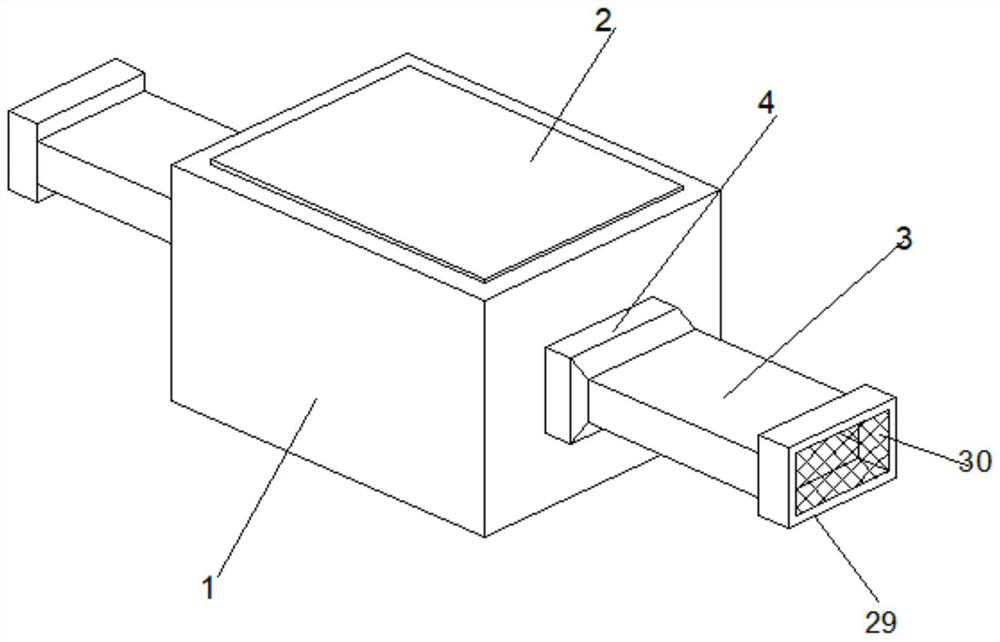
[0038] see Figure 1-7According to an embodiment of the present invention, an infrared optimal regeneration temperature device for a diesel soot particle filter body includes a filter regeneration chamber 1, and a sealing cover 2 is detachably provided on the filter regeneration chamber 1, and the filter regeneration chamber 1 Connecting pipes 3 are installed at both ends through a connecting structure 4, the connecting structure 4 includes a connecting shell 5, and an inner cavity 6 is arranged inside the connecting shell 5, and a limiting partition 7 is fixed inside the inner cavity 6, The limit partition 7 is provided with an opening 8, the upper and lower sides of the inner cavity 6 are provided with threaded holes 9, and the threaded holes 9 are provided with threaded rods 10, and the upper and lower sides of the connecting pipe 3 are A connecting thread groove 11 matching the threaded hole 9 is provided, and the limiting partition plate 7 is located on one side of the co...

Embodiment 2

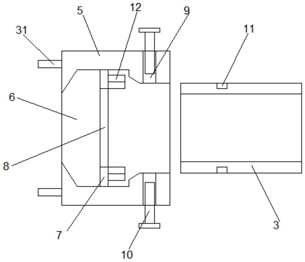
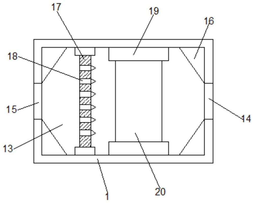
[0041] Such as figure 2 As shown, the filter regeneration chamber 1 is detachably provided with a sealing cover 2, and the two ends of the filter regeneration chamber 1 are equipped with connecting pipes 3 through the connection structure 4, the connection structure 4 includes a connection shell 5, and the connection The housing 5 is provided with an inner cavity 6, the inner cavity 6 is fixed with a spacer partition 7, the spacer spacer 7 is provided with an opening 8, and the upper and lower sides of the inner cavity 6 are provided with Threaded hole 9, threaded rod 10 is arranged in described threaded hole 9, and the upper and lower sides of described connecting pipeline 3 are all provided with connecting threaded groove 11 that matches with described threaded hole 9, and described limit partition 7 is positioned at the One side of the connecting pipe 3 is symmetrically provided with a position-limiting sealing structure 12, and a filter regeneration cavity 13 is provided ...

Embodiment 3

[0043] Such as Figure 6 As shown, the filter regeneration chamber 1 is detachably provided with a sealing cover 2, and the two ends of the filter regeneration chamber 1 are equipped with connecting pipes 3 through the connection structure 4, the connection structure 4 includes a connection shell 5, and the connection The housing 5 is provided with an inner cavity 6, the inner cavity 6 is fixed with a spacer partition 7, the spacer spacer 7 is provided with an opening 8, and the upper and lower sides of the inner cavity 6 are provided with Threaded hole 9, threaded rod 10 is arranged in described threaded hole 9, and the upper and lower sides of described connecting pipeline 3 are all provided with connecting threaded groove 11 that matches with described threaded hole 9, and described limit partition 7 is positioned at the One side of the connecting pipe 3 is symmetrically provided with a position-limiting sealing structure 12, and a filter regeneration cavity 13 is provided ...


PUM


Abstract

The invention discloses an infrared optimal regeneration temperature device for a soot particle filter of a diesel engine. The infrared optimal regeneration temperature device comprises a filtering regeneration bin, connecting pipelines are installed at the two ends of the filtering regeneration bin through connecting structures, each connecting structure comprises a connecting shell, an inner cavity is formed in each connecting shell, threaded holes are formed in the upper side and the lower side of each inner cavity, threaded rods are arranged in the threaded holes, a low-voltage heating element is installed in a filter regeneration cavity and at one side of an air outlet, and an infrared radiator is installed on the filter regeneration cavity. The infrared optimal regeneration temperature device has the advantages that the device is simple in structure and convenient to use, the electric energy utilization rate of infrared radiation heating of soot can be greatly increased, the regeneration time is short, the regeneration process is easy to optimize and control, the indexes of regeneration efficiency, regeneration temperature distribution, regeneration time and regeneration energy consumption are optimized at the same time, and meanwhile, replacement of a filtering device and installation and fixation of the connecting pipelines are facilitated.

Description

technical field [0001] The invention relates to the technical field of filtering soot particulates emitted by diesel engines, in particular to an infrared optimal regeneration temperature device for diesel soot particulate filters. Background technique [0002] At present, domestic and foreign soot particulate filter regeneration technologies include heavy load regeneration, catalytic regeneration, fuel injection combustion regeneration and electric heating regeneration. [0003] Among them, the method of large-load regeneration is relatively simple, but automobile diesel engines rarely work under such working conditions in actual use, and throttling reduces the power and economy of diesel engines to a large extent during the regeneration process, and due to Throttling increases the heat load of the cylinder head, piston, valve and other components, which has an adverse effect on the life of the diesel engine; when the metal oxides, the combustion products of the catalytic r...

Claims


Application Information

Patent Timeline
IPC IPC(8): F01N3/027F01N3/023F01N3/021F01N3/033F01N1/24F01N13/18
CPCF01N3/027F01N3/023F01N3/021F01N3/0335F01N1/24F01N13/1855F01N13/1838
Inventor 芮志英
Owner MAANSHAN CHANGLIFA MACHINERY MFG
Why Eureka
Try Eureka