
Traveling wave device configuration method and system based on topological structure layering

A topology and traveling wave technology, applied in special data processing applications, instruments, data processing applications, etc., can solve problems such as faulty branch judgment errors, different configuration schemes, high investment costs, etc., and achieve the effect of reducing the amount of installation

Pending Publication Date: 2021-11-23
JINING POWER SUPPLY CO OF STATE GRID SHANDONG ELECTRIC POWER CO +1
View PDF11 Cites 0 Cited by
  • Summary
  • Abstract
  • Description
  • Claims
  • Application Information

AI Technical Summary

Problems solved by technology

[0002] At the present stage in my country, the research on the configuration method of the device using fault traveling wave for positioning is mainly concentrated on the transmission network. At present, the structure of the distribution network is complex and changeable, with many branches. Due to investment restrictions, it is difficult to install traveling wave devices in each branch. , when a fault occurs on the line, there may be errors in the judgment of the fault branch, or even a false fault point is judged as the fault location. How to effectively configure the traveling wave device on the distribution network with complex branches, taking into account the positioning reliability and economy important practical significance
[0003] In the prior art, some literatures have proposed an optimal configuration method for configuring traveling wave devices in substations in the transmission network. Firstly, pre-configuration is performed according to the number of adjacent substations, and then the scheme is optimized in combination with the simulated annealing algorithm. However, when pre-configuration Different configuration schemes are easily affected by human factors, and the follow-up calculation is more complicated; there are literatures that analyze the degrees of freedom of traveling wave transmission in power grids, and optimize the configuration of traveling wave devices in combination with the degrees of freedom of traveling wave transmission, but the configuration The positioning result of the algorithm has a large error; some literatures analyze the shortest transmission path of the first wave of the fault based on graph theory, and then use the Floyd algorithm to convert the complex network into a simple network based on the principle of fault line reservation, and then the fault point will The line is divided into two sets, and then set the fault grouping for all lines and then take the smallest set to get the optimal solution for device configuration. However, this method needs to set faults for the entire line, which is slightly complicated; The selection problem is regarded as a multi-objective optimization combination problem. Constraint conditions are constructed through these two problems, and then the optimal configuration is obtained by solving with the binary particle swarm algorithm; Install the location, and then use the genetic algorithm to optimize the initial configuration scheme. Finally, if the scheme with the same number of device configurations is obtained, the scheme is optimized according to the configuration redundancy. However, this method does not explain how to choose the optimal scheme when the redundancy is the same. There are literatures that use network decomposition to decompose complex networks into simple tree networks and ring networks to obtain the optimal configuration of devices; there are literatures that use the range of zero-line mode time difference positioning to analyze the tree-type distribution network topology, The optimal configuration of the device is carried out by using the backward method, but the positioning is performed simply by using the difference in the wave velocity of the zero-line mode, and the error is relatively large
[0004] Most of the schemes proposed in the above documents are the optimal configuration of the transmission network, mainly for the configuration of devices installed in substations. For distribution networks with complex structures, it is often necessary to install devices on the substations at the end of the line to meet the positioning accuracy requirements. Therefore, it is of great engineering significance to study the distribution optimization of traveling wave devices on the distribution network to balance reliability and economy.

Method used


Image

  • Traveling wave device configuration method and system based on topological structure layering
  • Traveling wave device configuration method and system based on topological structure layering
  • Traveling wave device configuration method and system based on topological structure layering

Examples


Embodiment 1

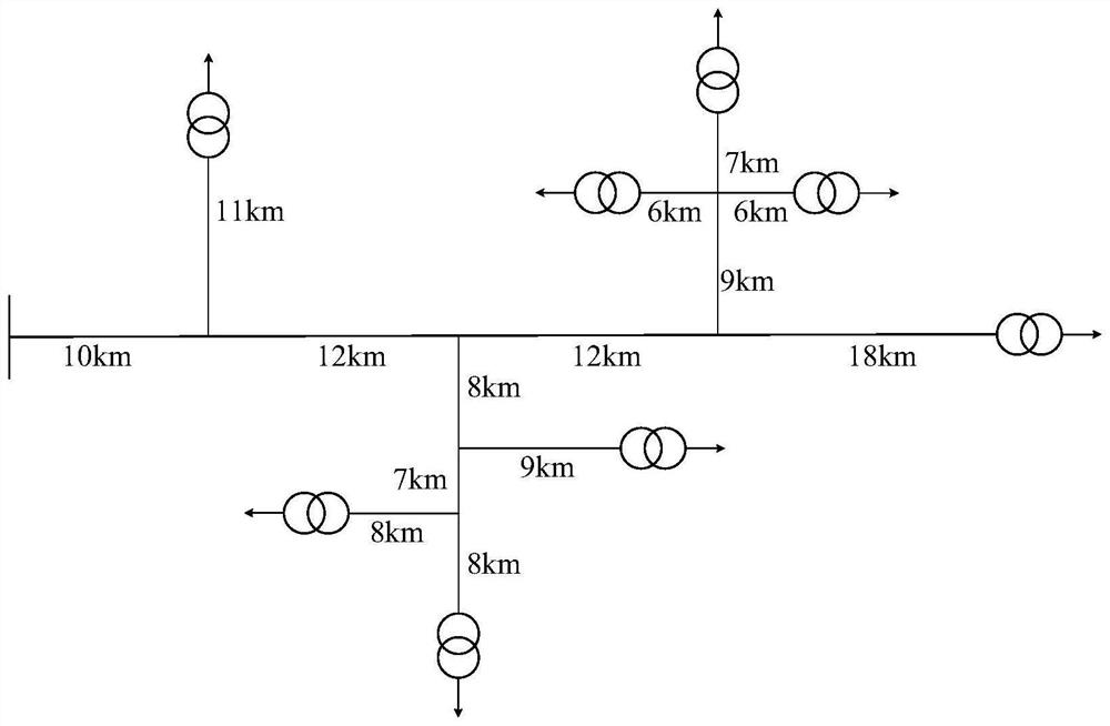
[0040] Embodiment 1 provides a method for configuring a traveling wave device based on topology layering, including the following steps:

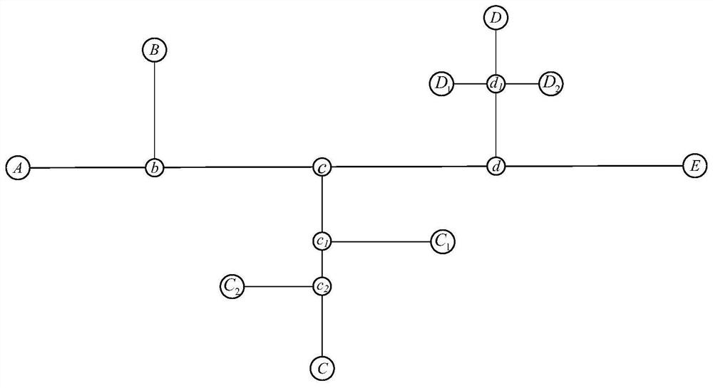
[0041] Step 1. Based on graph theory, the distribution network is expressed as a topological structure of an undirected weighted graph: the power supply, station area transformer, substation, and bifurcation node of the distribution line in the distribution network represent the undirected weighted graph. For the vertices of the graph, the distribution lines between the vertices represent the edges of the undirected weighted graph, and the length of the distribution lines between the vertices represents the weight of the edges, and the obtained undirected weighted graph is the topological structure of the distribution network picture;

[0042] The structure of the distribution network is complex, and most of them are radial tree structures. When analyzing the structure of the distribution network based on graph theory, the power system of t...

Embodiment 2

[0080] Embodiment 2 provides a traveling wave device configuration system based on topology layering, including:

[0081] The topology building block is used to represent the distribution network as an undirected weighted graph topology based on graph theory: the power supply in the distribution network, the transformer in the station area, the substation and the bifurcation nodes of the distribution line are all represented as undirected For the vertices of the directed weighted graph, the distribution line between the vertices represents the edge of the undirected weighted graph, and the length of the distribution line between the vertices represents the weight of the edge, and the obtained undirected weighted graph is the distribution network The topological structure diagram;

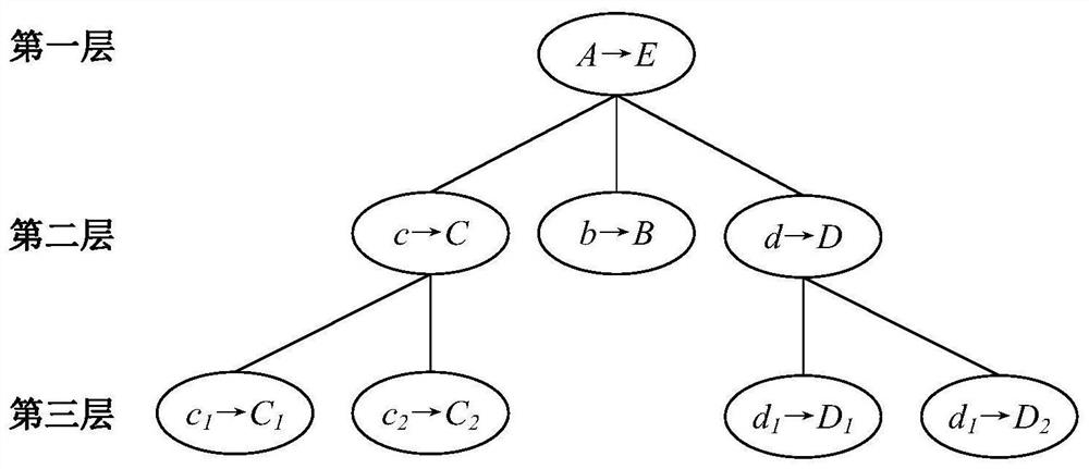
[0082] The layering module is used to layer the topological structure graph of the distribution network by using the graph theory layering method to obtain the layered structure graph of the distrib...


PUM


Abstract

The invention discloses a traveling wave device configuration method and system based on topological structure layering, and the method comprises the steps: enabling a power distribution network to be represented as a topological structure form of an undirected weighted graph based on a graph theory, i.e., enabling a power supply, a transformer area transformer, a transformer substation and a branch node of a power distribution line in the power distribution network to represent a vertex of the undirected weighted graph, enabling the distribution line between the vertexes to represent the edge of the undirected weighted graph, enabling the length of the distribution line between the vertexes to represent the weight of the edge, and enabling the obtained undirected weighted graph to be the topological structure graph of the power distribution network; layering the topological structure diagram of the power distribution network by using a graph theory layering method; finding independent branch lines, symmetrical independent branch lines and a complete T-shaped belt branch structure in the obtained power distribution network layered structure diagram; and carrying out traveling wave device configuration, wherein the asymmetric independent branch lines are not provided with the traveling wave device, any one of the symmetric independent branch lines is not provided with the traveling wave device, and the other lines are provided with the traveling wave devices. The installation amount of the traveling wave device can be reduced, and redundant positioning can be achieved.

Description

technical field [0001] The invention belongs to the technical field of distribution network fault monitoring resource configuration, and in particular relates to a method and system for configuring a traveling wave device based on topology layering. Background technique [0002] At the present stage in my country, the research on the configuration method of the device using fault traveling wave for positioning is mainly concentrated on the transmission network. At present, the structure of the distribution network is complex and changeable, with many branches. Due to investment restrictions, it is difficult to install traveling wave devices in each branch. , when a fault occurs on the line, there may be errors in the judgment of the fault branch, or even a false fault point is judged as the fault location. How to effectively configure the traveling wave device on the distribution network with complex branches, taking into account the positioning reliability and economy importa...

Claims


Application Information

Patent Timeline
IPC IPC(8): G06F30/18G06Q50/06
CPCG06F30/18G06Q50/06
Inventor 纪鹏志魏亚军刘宗杰张光耀王怀路牛浩川张道田柴环肖云东耿书波
Owner JINING POWER SUPPLY CO OF STATE GRID SHANDONG ELECTRIC POWER CO
Learn More