
Rotary locking structure capable of rotating at multiple angles for welding

A locking structure and multi-angle technology, applied in welding equipment, auxiliary welding equipment, welding/cutting auxiliary equipment, etc., can solve the problems of inability to adjust multiple angles, difficulty in height adjustment, and insufficient welding processing , to achieve the effect of easy adjustment of angle and height, convenient overall operation, fast splicing and assembly

Pending Publication Date: 2021-11-26
JIANGSU MARITIME INST
View PDF10 Cites 0 Cited by
  • Summary
  • Abstract
  • Description
  • Claims
  • Application Information

AI Technical Summary

Problems solved by technology

[0005] The object of the present invention is to provide a multi-angle rotating locking structure for welding, so as to solve the problem that the current welding device proposed in the background technology cannot perform good rotation locking on the pipeline during welding. During the locking process, the overall operation is relatively troublesome. At the same time, it is not possible to adjust multiple angles, and it is also difficult to adjust the height. Such equipment cannot meet the use of multiple angles of the pipeline during welding. Simultaneous welding The overall environment may be relatively complicated, and the pipes cannot be placed together well, and then the welding operation of the pipes can be realized. The overall use effect is relatively simple, which is not enough to meet the needs of welding processing.

Method used


Image

  • Rotary locking structure capable of rotating at multiple angles for welding
  • Rotary locking structure capable of rotating at multiple angles for welding
  • Rotary locking structure capable of rotating at multiple angles for welding

Examples


Embodiment Construction

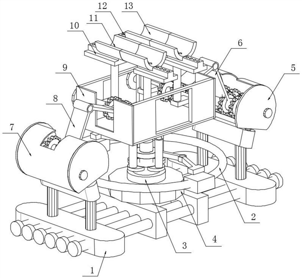
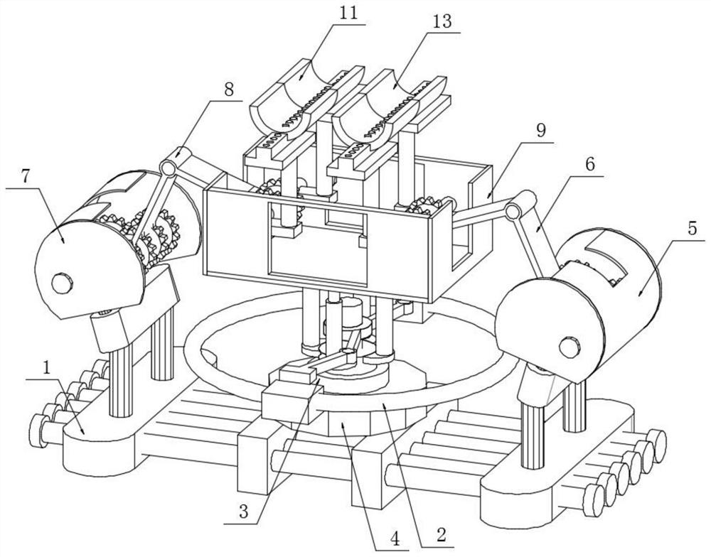
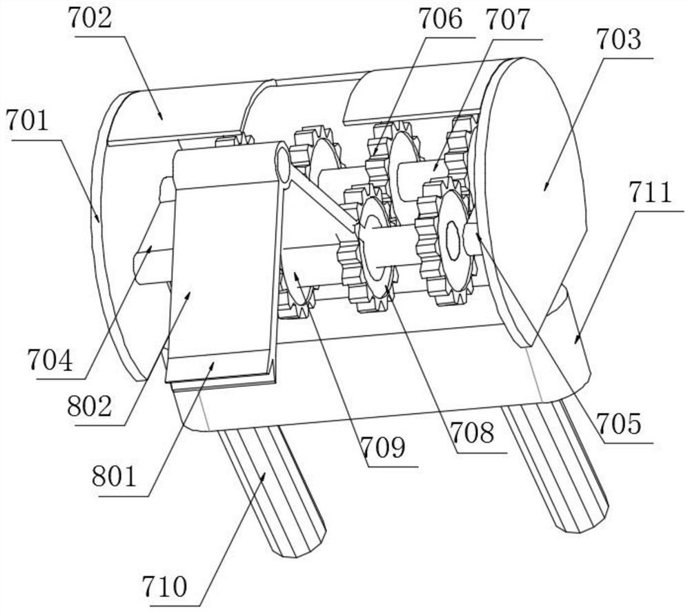
[0030] see Figure 1-8 , in an embodiment of the present invention, a multi-angle rotating welding rotation locking structure, including a support mechanism 1, a primary gear clamp 7 and a circuit control box 4, one end of the top surface of the support mechanism 1 is fixedly connected with a primary gear Clamp 7, the first-stage gear clamp 7 can play the role of clamping, the other end top surface of the support mechanism 1 is fixedly connected with the secondary gear clamp 5, the support mechanism 1 can play the effect of support, convenient Overall support, the inside of the first-stage gear clamp 7 is sleeved with a rotation locking mechanism B8, which can facilitate the overall clamping, and the other end of the rotation locking mechanism B8 is clamped with the lifting storage box 9, and lifting The placement box 9 is used for placing the pipes for lifting. The inside of the secondary gear clamp 5 is sleeved with a rotation locking mechanism A6. The rotation locking mecha...


PUM


Abstract

The invention discloses a rotary locking structure capable of rotating at multiple angles for welding, and relates to the field of welding machining. The rotary locking structure comprises a supporting mechanism, a first-stage gear clamping device and a circuit control box, the top face of one end of the supporting mechanism is fixedly connected with the first-stage gear clamping device, the top face of the other end of the supporting mechanism is fixedly connected with a second-stage gear clamping device, a rotary locking mechanism B is sleeved with the first-stage gear clamping device, and the other end of the rotary locking mechanism B is clamped with a lifting placing box. According to the rotary locking structure capable of rotating at multiple angles for welding, a traditional welding mode is changed, angle rotation and height lifting can be combined, meanwhile, pipelines can be locked, fixed and fused together, and the effect that one machine has multiple purposes can be achieved; and by means of the mode, rotary locking in the welding process can be more stable, meanwhile, angle and height adjustment is more convenient, the overall using effect is relatively good when pipeline welding operation is achieved, and the machining requirement can be well met.

Description

technical field [0001] The invention relates to the field of welding processing, in particular to a multi-angle rotating locking structure for welding. Background technique [0002] Welding, also known as welding, is a manufacturing process and technique that uses heat, high temperature, or pressure to join metal or other thermoplastic materials such as plastics. There are many sources of energy for modern welding, including gas flames, electric arcs, lasers, electron beams, friction, and ultrasound. In addition to its use in factories, welding can also be performed in a variety of environments, such as in the field, underwater and in space. Welding, wherever it occurs, can pose a hazard to the operator, so proper precautions must be taken when welding. Possible injuries caused by welding to the human body include burns, electric shock, visual impairment, inhalation of toxic gases, and excessive ultraviolet radiation. Welding achieves the purpose of joining through the fo...

Claims


Application Information

Patent Timeline
Patent Type & Authority Applications(China)
IPC IPC(8): B23K37/053
CPCB23K37/053B23K2101/06
Inventor 张强勇赵先锐董乃涵陈勇刘桂香朱征宇白津生贾向东毛琪钦康猛裴先峰宁显海
Owner JIANGSU MARITIME INST
Learn More