
Rapid transformation method and device for in-situ dry dedusting of blast furnace wet dedusting

A technology of wet dedusting and dry dedusting, which is applied to blast furnaces, dust collectors, blast furnace details, etc., can solve problems such as smoothness, rationality, safety impact, tight time, and short blast furnace overhaul period of the gas pipeline system, and achieve The effect of eliminating safety and quality risks, abundant time and saving construction period

Active Publication Date: 2021-11-26
MAANSHAN IRON & STEEL CO LTD
View PDF1 Cites 0 Cited by
  • Summary
  • Abstract
  • Description
  • Claims
  • Application Information

AI Technical Summary

Problems solved by technology

However, in recent years, blast furnace rapid and integrated overhaul technology has gradually occupied the stage. In this case, due to the short and tight time for blast furnace overhaul and limited by the site, it is difficult to complete the original wet dedusting within a short overhaul period. If you choose another location to build dry dust removal, the rationality of the gas piping system will be broken, which may have a great impact on the smoothness, rationality, and safety of the gas piping system
Therefore, under the current mode of rapid overhaul of blast furnaces, it is impossible to carry out the transformation and construction of dry dedusting. Generally, the rapid overhaul process is adopted, and the wet dedusting system is still retained. This is also a bottleneck of the current rapid overhaul of blast furnaces.

Method used


Image

  • Rapid transformation method and device for in-situ dry dedusting of blast furnace wet dedusting
  • Rapid transformation method and device for in-situ dry dedusting of blast furnace wet dedusting
  • Rapid transformation method and device for in-situ dry dedusting of blast furnace wet dedusting

Examples


Embodiment

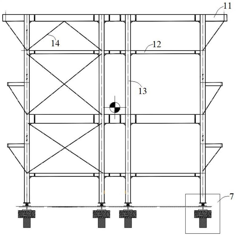
[0040] combine figure 1 , a kind of device of the present invention that is used for blast furnace wet dedusting in situ to perform dry dedusting rapid transformation, comprising a new dedusting frame 1, a frame foundation 5 built on the original wet dedusting site and a frame for moving the dedusting frame 1 Push structure 7; said push structure 7 is arranged on the lower part of the bottom frame 3 at the bottom of the dust removal frame 1 to support the bottom frame 3; the upper part of the frame foundation 5 is equipped with a column foundation 6; the dust removal frame 1 is temporarily fixed beside the frame foundation 5 , The dust removal frame 1 is connected with the frame foundation 5 by a track 4 .

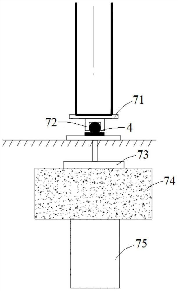
[0041] combine image 3 , in this embodiment, the pushing structure 7 includes a bottom plate 71, a card slot 72, a section steel 73, a platform 74 and a pile foundation 75; the bottom plate 71 is arranged at the bottom of the dust removal frame 1 and carries the column 1...


PUM


Abstract

The invention discloses a rapid transformation method and device for in-situ dry dedusting of blast furnace wet dedusting, and belongs to the technical field of gas system transformation. The device comprises a dust removal frame, a frame foundation built on an original wet dust removal site and a pushing and moving structure used for moving, the pushing and moving structure is arranged at the lower part of a bottom frame at the bottom of the dust removal frame and supports the bottom frame, a stand column foundation is built on the upper portion of the frame foundation, the dust removal frame is temporarily fixed beside the frame foundation, and the dust removal frame is connected to the frame foundation through rails. According to the rapid transformation method and device, construction of a dry-method dust removal structure and equipment is completed before furnace shutdown, construction of a dry-method dust removal foundation and part of the translation rails is only conducted after the furnace shutdown, the dry-method dust removal system structure is connected to the foundation through the rail translation technology, and finally dry-method dust removal transformation is completed, so that the construction period is greatly shortened, and the transformation of dry dust removal and wet dust removal in situ is completed within the limited time of overhaul of the blast furnace.

Description

technical field [0001] The invention relates to the technical field of gas system reformation, in particular to a method and device for quick reformation of blast furnace wet dedusting in situ dry dedusting. Background technique [0002] In the metallurgical industry, a large amount of raw coal gas is produced during blast furnace production, and the pressure is generally 0.2Mpa-0.25Mpa. Before being merged into the gas pipeline network, the raw coal gas must be purified and dust-removed. The traditional process is to use gravity dust removal for primary dust removal, and Venturi scrubber or annular seam scrubber for wet secondary dust removal. After the gas purified by the scrubber is used for power generation through TRT (residual pressure turbine), it is converted to low pressure The state of the gas is merged into the gas pipeline network. [0003] Venturi scrubber or annular seam scrubber, washing water discharge is a problem that is difficult to solve completely. Wit...

Claims


Application Information

Patent Timeline
Patent Type & Authority Applications(China)
IPC IPC(8): C21B7/22
CPCC21B7/22C21B7/002C21B2100/44
Inventor 张全一曹兵
Owner MAANSHAN IRON & STEEL CO LTD
Learn More