A 3D HTS Supergain Antenna Based on Resonant Ring

A high-temperature superconducting and resonant ring technology, applied in antennas, antenna parts, usage of superconductor elements, etc., can solve the problems of low gain, low antenna efficiency, low directivity, etc., to achieve super gain and improve directivity , high directional effect

Active Publication Date: 2022-06-03
SICHUAN UNIV
View PDF12 Cites 0 Cited by
  • Summary
  • Abstract
  • Description
  • Claims
  • Application Information

AI Technical Summary

Problems solved by technology

The antenna does not use a resonant ring structure, the directivity is relatively low, and the efficiency of the antenna is low, resulting in low gain

Method used


Image

  • A 3D HTS Supergain Antenna Based on Resonant Ring
  • A 3D HTS Supergain Antenna Based on Resonant Ring
  • A 3D HTS Supergain Antenna Based on Resonant Ring

Examples


Embodiment Construction

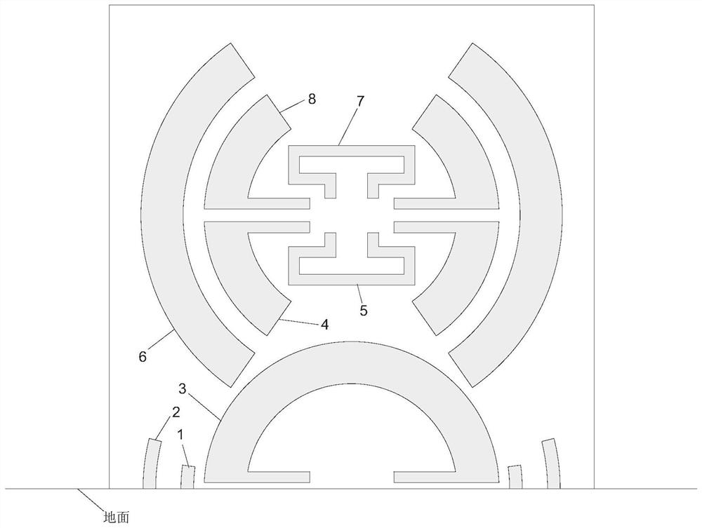
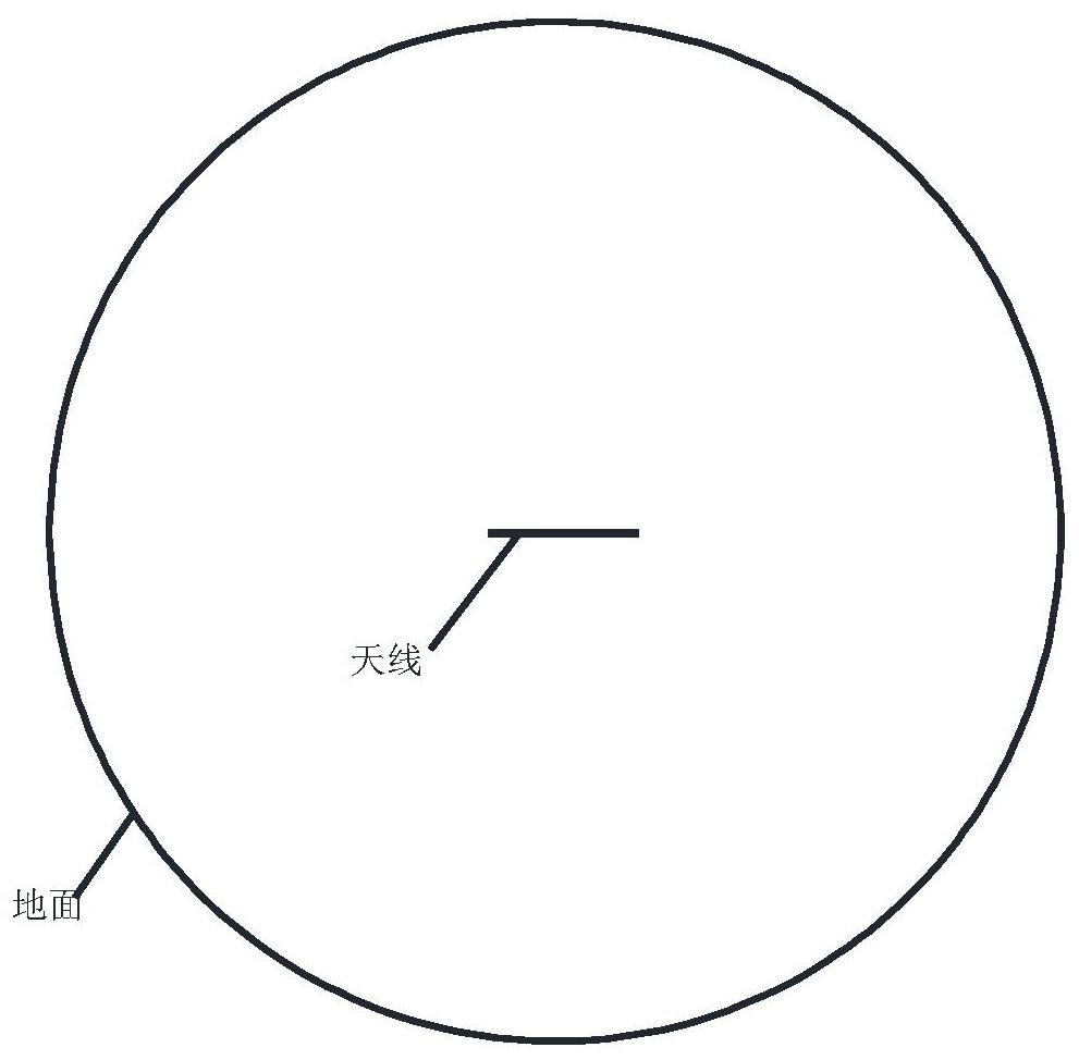
[0031] The dielectric substrate stands on the metal floor and is placed vertically with the metal floor; the shape of the metal floor is a circle, and the dielectric substrate

[0039] The first arc-shaped monopole 1 or the third arc-shaped monopole is fed by means of 50Ω coaxial line feeding.

[0040] The radiation structure of the antenna described in this embodiment adopts dysprosium barium copper oxide (DyBCO) superconducting film, and the dielectric substrate adopts aluminum

[0041] The dielectric constant of the dielectric substrate of this embodiment is about 24 in a 77K liquid nitrogen environment, and the thickness of the substrate is 0.5 mm.

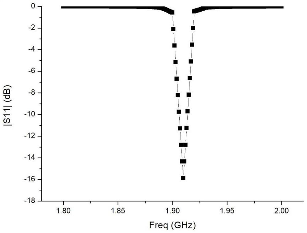
[0043] Use HFSS to simulate the antenna described in this embodiment. The S-parameter of the antenna is shown in Figure 3, at 1.91GHZ frequency


PUM


Abstract

The invention discloses a three-dimensional high-temperature superconducting super-gain antenna based on a resonance ring, and belongs to the technical field of high-temperature superconducting super-gain antennas. The antenna of the present invention includes a radiation structure, a dielectric substrate and a metal floor; the dielectric substrate stands on the metal floor, and the shape of the metal floor is circular; the radiation structure is located on the vertical surface of the dielectric substrate and is an axisymmetric structure, including four arcs Monopole, single-slit circular resonant ring, two double-slit circular resonant rings, two rectangular-slit circular resonators, and double-slit circular resonant rings. The antenna of the present invention uses an arc-shaped monopole to couple and feed the resonant ring, the input impedance is adjustable, and has excellent tuning ability; the resonant ring structure is used to achieve high directivity, and each resonant ring is coupled to achieve miniaturization and improve The purpose of directivity, so that the antenna achieves super directivity, and then the super gain of the antenna is realized by using superconducting materials to make the antenna almost lossless.

Description

A three-dimensional high-temperature superconducting supergain antenna based on resonant ring technical field The invention belongs to the high temperature superconducting super-gain antenna technical field, be specifically related to a kind of three-dimensional high temperature based on resonant ring Superconducting supergain antenna. Background technique [0002] In general, as the aperture area of ​​the antenna becomes smaller, its gain will also decrease as the size becomes smaller. when a day When the gain of the wire is greater than the theoretical maximum gain of the size of the antenna, the antenna is called a super-gain antenna. super gain antenna The main advantage is that the size of the antenna is greatly reduced, which not only reduces the footprint, but also saves the time required to build the antenna. The cost and maintenance work can also be greatly reduced. Moreover, under the same circumstances, the higher the gain of the antenna, the higher the t...

Claims


Application Information

Patent Timeline
Patent Type & Authority Patents(China)
IPC IPC(8): H01Q1/36H01Q1/38H01Q1/50H01Q1/00
CPCH01Q1/364H01Q1/38H01Q1/50H01Q1/002Y02E40/60
Inventor 卢萍黄卡玛
Owner SICHUAN UNIV
Why Eureka
Try Eureka