
Anisotropic flow shallow layer rotary sedimentation tank

A rotary and sedimentation tank technology, which is applied in the direction of sedimentation separation, sedimentation tank, feeding/discharging device of the sedimentation tank, etc., can solve the problem of affecting the effective settlement of suspended solids, low space utilization of the sedimentation tank, and reduced sedimentation space of the sedimentation tank and other problems, to achieve good settling performance, convenient collection and discharge, and improve the effect of settling performance

Inactive Publication Date: 2021-11-30
TAIZHOU UNIV
View PDF0 Cites 0 Cited by
  • Summary
  • Abstract
  • Description
  • Claims
  • Application Information

AI Technical Summary

Problems solved by technology

The tank shape of the inclined plate sedimentation tank is usually rectangular. The bottom of the tank body is filled with water, and the upper tank body overflows with water. The rising water flow between the inclined plates affects the downward settlement of particles and the effective settlement of suspended solids, resulting in some Suspended solids flow out with the water flow, affecting the quality of the effluent
[0005] (2) The space utilization rate of the sedimentation tank is low
In the traditional sloping plate sedimentation tank, the sloping plates cover the entire surface of the sedimentation tank along an inclined direction, but due to the consistent arrangement direction, there is inevitably an idle space at both ends of the sloping plate near the vertical tank wall, so that the sedimentation tank is effective. Reduced settling space

Method used


Image

  • Anisotropic flow shallow layer rotary sedimentation tank
  • Anisotropic flow shallow layer rotary sedimentation tank
  • Anisotropic flow shallow layer rotary sedimentation tank

Examples


Embodiment Construction

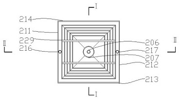
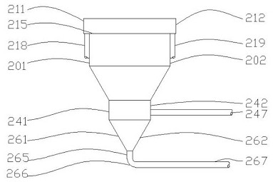
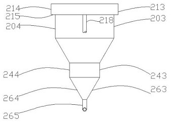
[0027] The following are specific embodiments of the present invention and in conjunction with the attached figure 1 ~ attached Figure 8 , to further describe the technical solutions of the present invention, but the present invention is not limited to these embodiments.

[0028] A kind of reverse flow shallow rotary sedimentation tank, including the upper water inlet area 20, the outer drainage tank 21, the middle sedimentation area 22, the lower buffer zone 24, the bottom mud collection area 26, the vertical The centerlines coincide.

[0029] The water inlet area 20 includes a left wall panel 201 , a right wall panel 202 , a front wall panel 203 , a rear wall panel 204 , a water outlet hole 205 , a water inlet vertical pipe 206 , and a water inlet bell mouth 207 . The left wall plate 201, the right wall plate 202, the front wall plate 203 and the rear wall plate 204 are all rectangular thin plates with the same size. The vertical sides of the left wall plate 201 , the ri...


PUM


Abstract

The invention discloses an inclined plate sedimentation tank with annularly and rotatably arranged inclined plates, and particularly relates to a high-integration-level integrated anisotropic flow shallow layer rotary sedimentation tank device in which water enters from the center of the upper part of the inclined plate, overflows from the periphery of the top of a water inlet area and discharges water, and the rotary inclined plate is inclined towards the central part from top to bottom. The tank comprises an upper water inlet area, an outer drainage groove, a middle settling area, a lower buffer area and a bottom sludge collecting area, and the vertical center lines of the five areas coincide; the outer side of the water inlet area is connected with a bottom plate of the drainage groove; the settling area is of an open hollow inverted quadrangular frustum pyramid structure, and an annular rotary inclined plate is arranged in the settling area; the buffer area is of a hollow cuboid structure with upper and lower openings; the sludge collecting area is of a space structure which is provided with an open rectangular upper end and an open circular lower end and is transited from a hollow inverted quadrangular frustum pyramid to a hollow inverted circular truncated cone. The sedimentation tank has the advantages of good suspended matter settling performance and concentrated settling paths.

Description

technical field [0001] The invention belongs to the field of water supply and drainage science and engineering, and provides a counterflow inclined plate sedimentation tank for sedimentation treatment of suspended matter in water, in particular to a counterflow shallow layer with shallow sedimentation function and high integration Rotary sedimentation tank device. Background technique [0002] Sedimentation tank is a primary treatment or advanced treatment structure commonly used in water purification process. It is mainly used to remove suspended solids with relatively high density from the water body by gravity. The shallow sedimentation theory holds that the shallower the pool depth of the sedimentation tank, the shorter the sedimentation time, the greater the surface load, the higher the sedimentation efficiency, and the smaller the particle size of the suspended solids that can be removed. According to this principle, installing inclined plates (or inclined tubes) in t...

Claims


Application Information

Patent Timeline
IPC IPC(8): B01D21/02B01D21/24B01D21/00
CPCB01D21/02
Inventor 刘树元刘慧谢雯冰岳梦雪
Owner TAIZHOU UNIV
Learn More