Waste gas treatment device for UV photocureable coating equipment

A waste gas treatment device and light-curing coating technology, which is applied in steam condensation, chemical instruments and methods, and separation of dispersed particles, can solve problems such as energy loss, poor condensation effect, and heat change, and achieve sufficient cooling and stability. Effect

Pending Publication Date: 2021-11-30
瑞润化工(南通)有限公司
View PDF0 Cites 0 Cited by
  • Summary
  • Abstract
  • Description
  • Claims
  • Application Information

AI Technical Summary

Problems solved by technology

[0005] The purpose of the present invention is to address the deficiencies of the prior art. By setting the cooling assembly to cooperate with the fourth transmission assembly, when the second control valve is fully opened, the drive mechanism uses the fourth transmission assembly to synchronously drive the cooling assembly to work. When the cooling assembly When swinging to the vertical state of the heat exchanger, the exhaust gas is blocked at the inlet end of the heat exchanger. Since the air outlet of the fan is closed at this time, the pressure of the inlet end of the entire heat exchanger reaches a constant level, and then set at this time The manometer can send out an alarm, and manually adjust the temperature in the heat exchanger to cool down. When the exhaust gas reaches a temperature that satisfies the conditions, the switching plate rotates, and the exhaust gas enters the output mechanism, thus solving the problem of condensing the heat exchanger in the heat exchanger. When the exhaust gas is exhausted, the condensed water will become hot after heat exchange with the exhaust gas. If it is not removed in time, the heated wastewater will cause poor condensation effect in the heat exchanger; if it is removed in time, the hot water will directly enter the cold water tower and cause a The cold water becomes hot, and the technical problem of serious energy loss

Method used


Image

  • Waste gas treatment device for UV photocureable coating equipment
  • Waste gas treatment device for UV photocureable coating equipment
  • Waste gas treatment device for UV photocureable coating equipment

Examples


Embodiment 1

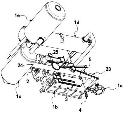
[0054] like figure 1 As shown, the waste gas treatment device of UV photocuring coating equipment includes a fan 1a, a heat exchanger 1b, a rotary separator 1c, a cooling tower 1d, and a gas-liquid mixing tower 1e, and is also provided in communication with the rotary separator 1c and used for The switching mechanism 2 for automatically splitting the exhaust gas at different temperatures, the cooling mechanism 3 arranged in the heat exchanger 1b and driven along the length direction of the heat exchanger 1b, and the heat exchanger 1b and the rotating The heat dissipation mechanism 4 for pre-cooling the heated water in the separator 1c, the water outlet 4a of the heat dissipation mechanism 4 is communicated with the cold water tower 1d and its water inlet 4b is communicated with the heat exchanger 1b;

[0055] The switching mechanism 2 includes a tee 21 arranged on the upper end of the heat exchanger 1b, a switching plate 22 installed in the center of the transition of the tee ...

Embodiment 2

[0093] like Figure 11 As shown, the components that are the same as or corresponding to those in the first embodiment are marked with the corresponding reference numerals in the first embodiment. For the sake of simplicity, only the differences from the first embodiment will be described below. The difference between this embodiment two and embodiment one is:

[0094] further, such as Figure 11 As shown, the cooling assembly includes several sets of first rotating assembly 31a and second rotating assembly 31b arranged at equal intervals along the length direction of the heat exchanger 1b and alternately arranged. The first rotating assembly 31a and the second rotating assembly The rotation direction of the assembly 31b is opposite and each includes a swing plate 311 rotatably arranged on the heat exchanger 1b, a pulley with one end fixedly connected to the swing plate 311 and the other end fixedly connected to the side wall of the heat exchanger 1b. The spring 312 and the ...


PUM


Abstract

The invention relates to a waste gas treatment device for UV photocureable coating equipment. The devicecomprises a fan, a heat exchanger, a rotary separator, a cold water tower and a gas-liquid mixing tower, and further comprises a switching mechanism, a cooling mechanism and a heat dissipation mechanism; a water outlet of the heat dissipation mechanism is communicated with the cold water tower, and a water inlet of the heat dissipation mechanism is communicated with the heat exchanger and the rotary separator; the switching mechanism comprises a tee joint, a switching plate, a circulating mechanism, an output mechanism and a temperature control precision meter; and an adjusting assembly is further arranged at the air outlet of the fan and used for controlling the air outlet amount of the air outlet. The waste gas treatment device solves the technical problems that when waste gas in the heat exchanger is condensed, condensed water becomes hot after heat exchange with the waste gas, and if the condensed water is not discharged in time, the heated waste water can cause the poor condensation effect in the heat exchanger; and that even if the condensed water is discharged in time, the hot water directly enters the cold water tower, cold water in the cold water tower becomes hot, and energy loss is serious.

Description

technical field [0001] The invention relates to the technical field of exhaust gas recovery equipment, in particular to an exhaust gas treatment device for UV photocuring coating equipment. Background technique [0002] Light-curing coatings, also known as photosensitive coatings, use ultraviolet light as the energy source for coating curing, also known as UV-curing coatings. photocurable coating(s); phototensitzing coatings do not require heating, and can be quickly cured to form a film on flammable substrates such as paper, plastic, leather and wood. It is mainly composed of photosensitive resin, photosensitizer (photoinitiator) and diluent, and some additives such as heat stabilizer are added at the same time, and pigments and fillers are added when preparing color paint. Photosensitive resins are generally low molecular weight resins with unsaturated bonds, such as unsaturated polyesters, acrylic oligomers; photosensitizers are compounds that easily absorb ultraviolet l...

Claims


Application Information

Patent Timeline
IPC IPC(8): B01D53/00B01D53/18B01D53/78B01D5/00B01D45/14
CPCB01D5/00B01D53/002B01D53/78B01D53/18B01D45/14Y02P70/10
Inventor 林易
Owner 瑞润化工(南通)有限公司
Why Eureka
Try Eureka