Efficient recycling and regenerating treatment process for waste solar heat collector

A solar collector and solar collector tube technology, applied in the field of solar energy, can solve the problems of difficulty in ensuring that the inner wall of the collector tube is cleaned, the efficiency of the collector tube is low, etc., so as to reduce the labor workload of workers, improve the high-efficiency recovery efficiency, and improve the high-efficiency recovery and recycling rate. The effect of using

Active Publication Date: 2021-11-30
山东沐阳新能源有限公司
View PDF9 Cites 0 Cited by
  • Summary
  • Abstract
  • Description
  • Claims
  • Application Information

AI Technical Summary

Problems solved by technology

[0007] In view of the problems in the prior art, the purpose of the present invention is to provide a process for efficient recovery and regeneration of waste solar collectors, which solves the problem that the inner tube and outer tube of the vacuum tube are made of glass when the collector tube is recycled, which can be recycled and reused. When recycling, you only need to pull out the asbestos plug on the waste solar collector from the inner tube of the vacuum tube, and you only need to clean it before recycling. However, the existing cleaning and processing of the collector tube is mainly done manually. Manually separate and clean each heat collecting tube. This operation method makes the efficiency of heat collecting tubes low when recycling, and manual cleaning is difficult to ensure that the inner wall of each heat collecting tube is cleaned.

Method used


Image

  • Efficient recycling and regenerating treatment process for waste solar heat collector
  • Efficient recycling and regenerating treatment process for waste solar heat collector
  • Efficient recycling and regenerating treatment process for waste solar heat collector

Examples


Embodiment 1

[0049] see Figure 1-9 It is a schematic diagram of the overall structure of a high-efficiency recovery and regeneration process for waste solar collectors;

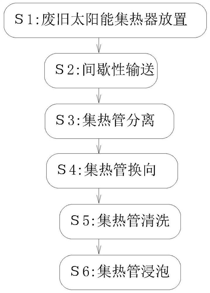
[0050] A high-efficiency recovery and regeneration treatment process for waste solar heat collectors, comprising the following steps:

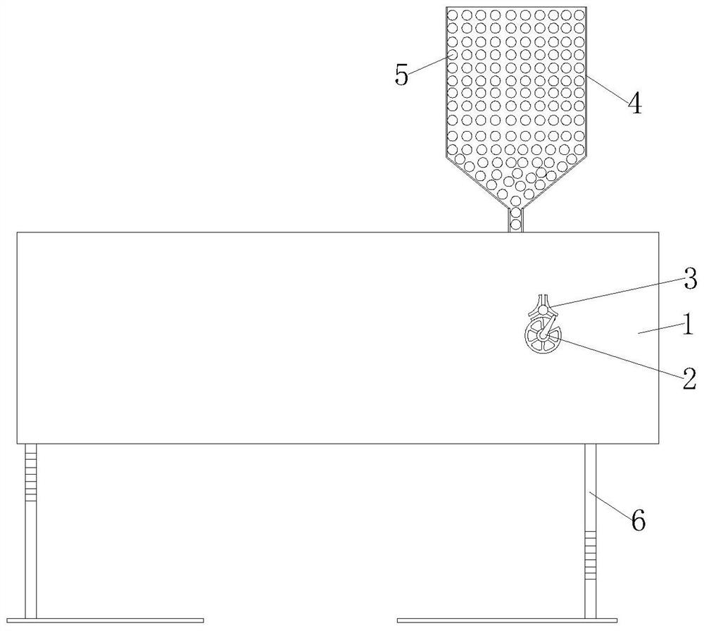
[0051] S1. Placement of waste solar heat collectors: collect the waste solar heat collectors in the waste heat collector storage bucket 4, and make the two ends of each waste solar heat collectors consistent;

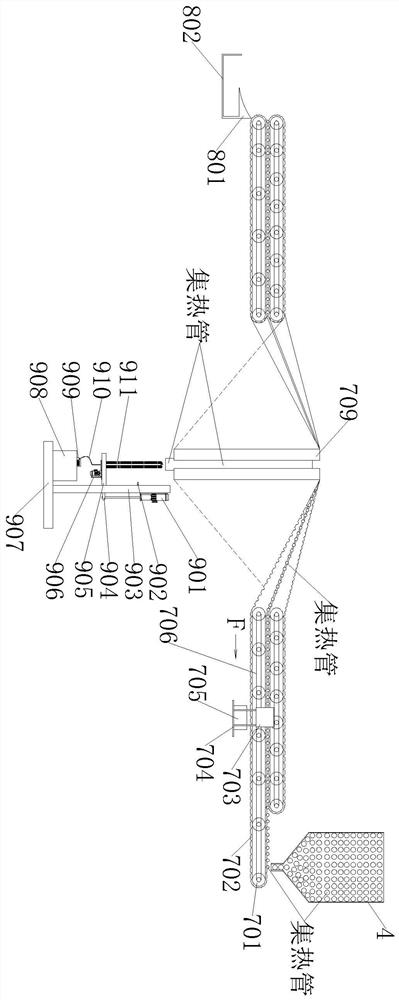
[0052] S2. Intermittent transportation: intermittently move the waste solar heat collecting tubes placed in the waste heat collecting tube storage bucket 4 through the intermittent conveying mechanism 7 in step S1;

[0053] S3. Separation of heat collecting tubes: separate each waste solar heat collecting tube that moves intermittently in step S2, by absorbing the asbestos plug at the front end of the waste Pull out, so as to realize the separation of the vacuum tube inner tube ...


PUM


Abstract

The invention provides an efficient recycling and regenerating treatment process for a waste solar heat collector, and relates to the technical field of solar energy. The process comprises the following steps that S1, the waste solar heat collector is placed, waste solar heat collecting pipes are collected in a waste heat collecting pipe storage hopper, and the two ends of each waste solar heat collecting pipe are made to be placed in a consistent manner; and S2, intermittent conveying is conducted, the waste solar heat collecting pipes placed in the waste heat collecting pipe storage hopper in the step S1 are intermittently moved through an intermittent conveying mechanism. The top end of a rotating shaft of a steel wire roller and the top end of a rotating shaft of a sweeping roller are each fixedly provided with two dehairing rods, the inner walls of the top ends of the rotating shafts are shoveled through chip shoveling cutters at the top ends of the two dehairing rods, and viscous substances attached to the top ends of the inner walls of the waste solar heat collecting pipes are shoveled through cutting edges on the two sides of the chip shoveling cutters. Therefore the viscous substances at the top ends of the inner walls of the solar heat collecting pipes are removed, and the inner walls of the solar heat collecting pipes are cleaned better.

Description

technical field [0001] The invention relates to the technical field of solar energy, in particular to a high-efficiency recovery and regeneration treatment process for waste solar heat collectors. Background technique [0002] A solar collector is a device that converts the sun's radiant energy into heat energy. Because the solar energy is relatively scattered, it must be concentrated, so the heat collector is a key part of various solar energy devices. Due to different purposes, collectors and their matching systems are divided into many types with different names, such as solar cookers for cooking, solar water heaters for hot water, solar dryers for drying items, solar dryers for Solar furnaces for melting metals, as well as solar houses, solar thermal power plants, solar desalination plants, and more. [0003] Existing solar collectors on the market commonly include flat-plate collectors and vacuum tube collectors, and the structures of vacuum tube collectors mainly inc...

Claims


Application Information

Patent Timeline
Patent Type & Authority Applications(China)
IPC IPC(8): B09B3/00B09B5/00B08B9/043B08B13/00
CPCB09B3/00B09B5/00B08B9/043B08B13/00Y02W30/20Y02W30/82
Inventor 李旋
Owner 山东沐阳新能源有限公司
Why Eureka
Try Eureka