Clamping device for intelligent power battery of new energy vehicles

A technology for new energy vehicles and power batteries, which is applied in workpiece clamping devices, battery assembly machines, and secondary battery manufacturing. , the effect of easy clamping

Active Publication Date: 2022-04-29
杭州巍枫减速机械有限公司
View PDF12 Cites 0 Cited by
  • Summary
  • Abstract
  • Description
  • Claims
  • Application Information

AI Technical Summary

Problems solved by technology

[0004] Based on this, it is necessary to address the above problems and propose a new energy vehicle intelligent power battery clamping device that can clamp power batteries of different sizes and can automatically and efficiently arrange the power batteries evenly, so as to solve the above-mentioned problems in the background technology. In the prior art, different clamping machines need to be replaced to clamp power batteries of different sizes, and it is difficult to ensure accurate assembly of power batteries

Method used


Image

  • Clamping device for intelligent power battery of new energy vehicles
  • Clamping device for intelligent power battery of new energy vehicles
  • Clamping device for intelligent power battery of new energy vehicles

Examples


Embodiment 1

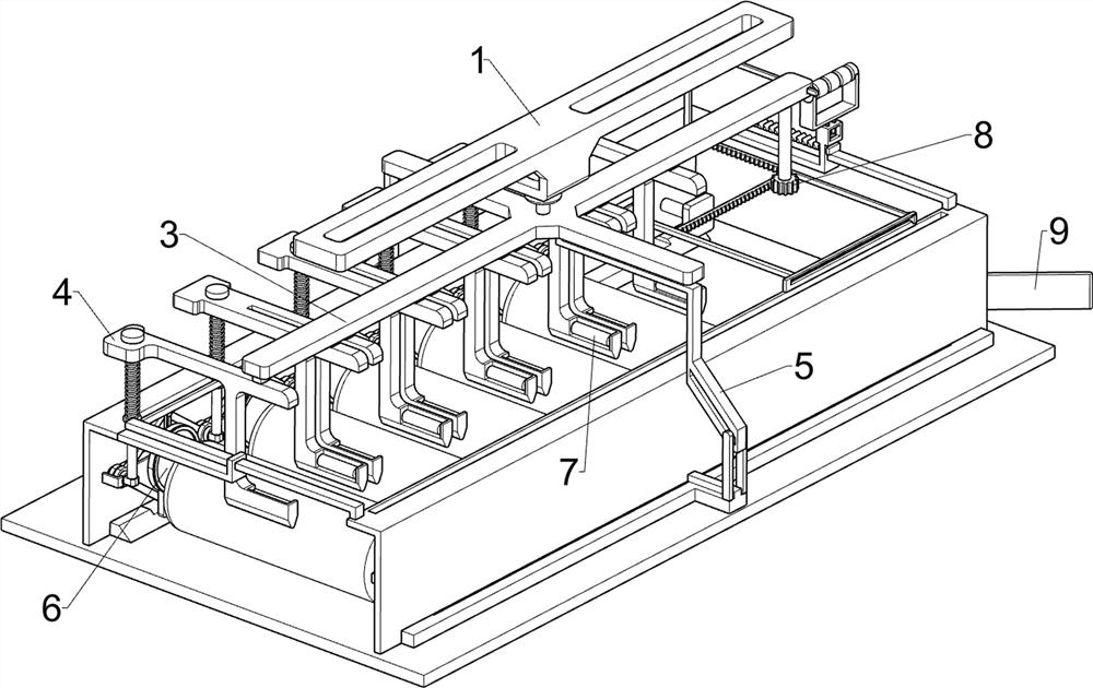
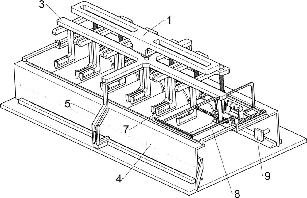
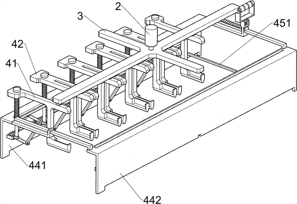
[0038] The clamping device of the intelligent power battery of the new energy vehicle, such as figure 1 , figure 2 , image 3 , Figure 4 , Figure 5 , Image 6 , Figure 7 , Figure 8 , Figure 9 with Figure 10 As shown, it includes a first fixed frame 1, an electric push rod 2, a cross 3, an arrangement mechanism 4 and a shoveling mechanism 5, an electric push rod 2 is fixedly connected under the first fixed frame 1, and one end of the telescopic shaft of the electric push rod 2 passes through The cross 3 is connected by welding, the cross 3 is provided with an arrangement mechanism 4 for evenly arranging the power batteries, and the cross 3 is provided with a scooping mechanism 5 for scooping up the power batteries.

[0039] The arrangement mechanism 4 includes a first sliding frame 41, a second sliding frame 42, a slide bar 43, a first return spring 44, a fixed side plate 441, a sliding side plate 442, a sliding block 45, a connecting bar 451, a connecting plate ...

Embodiment 2

[0044] On the basis of Example 1, such as Figure 11 , Figure 12 with Figure 13 As shown, a clamping mechanism 6 is also included. The clamping mechanism 6 is arranged on the side where the fixed side plate 441 and the sliding side plate 442 are close to each other. The clamping mechanism 6 is used to better clamp the power battery. The clamping mechanism 6 includes a sliding bar 61, a sliding splint 62 and a rubber ring 63. The fixed side plate 441 and the sliding side plate 442 are linearly distributed inside and are slidably connected with five sliding bars 61. The sliding bar 61 is located between the fixed side plate 441 and the On the sides where the sliding side plates 442 are close to each other, the sliding bar 61 is slidably matched with the telescopic frame 47. The sliding splint 62 is slidably connected to the sliding bar 61. The sliding splint 62 is used to clamp the power battery, and the sliding splint 62 passes through the sliding In the bar 61 , the right ...

Embodiment 3

[0047] On the basis of Example 2, such as Figure 14 As shown, it also includes an anti-scratch roller 7, the bottom of the first sliding frame 41 is rotatably connected with the anti-scratch roller 7, the bottom of the second sliding frame 42 is rotatably connected with a pair of anti-scratch rollers 7, the anti-scratch roller 7 Used to prevent the surface of the power battery from being scratched.

[0048] During the downward movement of the first carriage 41 and the second carriage 42, the anti-scratch roller 7 in contact with the power battery will roll through the anti-scratch roller 7 to prevent the surface of the power battery from being scratched.


PUM


Abstract

The invention relates to a clamping device, in particular to a clamping device for an intelligent power battery of a new energy vehicle, including a first fixing frame, an electric push rod, a cross, an arrangement mechanism, etc.; A cross is fixedly connected to one end of the telescopic shaft of the electric push rod, and an arrangement mechanism is arranged on the cross. Due to the equal distance between the adjacent first sliding frame and the second sliding frame, and the two adjacent second sliding frames, the first sliding frame and the second sliding frame will squeeze the power battery, so that the power battery can The uniform arrangement facilitates the subsequent accurate assembly of the power battery, and achieves the purpose of automatically and efficiently arranging the power battery evenly.

Description

technical field [0001] The invention relates to a clamping device, in particular to a clamping device for an intelligent power battery of a new energy vehicle. Background technique [0002] Under the pressure of energy and environmental protection, new energy vehicles have developed rapidly. Power batteries have replaced gasoline and diesel as the driving power source of electric vehicles. With the rapid development of new energy vehicles, the demand for new energy vehicle power batteries continues Rapid expansion, in the process of producing power batteries, in order to increase the output of power batteries, the assembly of new energy power batteries also needs to develop in the direction of intelligence. [0003] The existing technology completes the assembly of new energy vehicle power batteries by machines, and the power battery needs to be clamped during the assembly process. However, due to the diversification of new energy vehicle power batteries, the size of new ene...

Claims


Application Information

Patent Timeline
Patent Type & Authority Patents(China)
IPC IPC(8): B25B11/02B23P19/00H01M10/04
CPCB25B11/02B23P19/00H01M10/0404Y02P70/50
Inventor 况丹丹
Owner 杭州巍枫减速机械有限公司
Why Eureka
Try Eureka