Connection auxiliary equipment for transmission with driving belt pulley

A technology for driving pulleys and auxiliary equipment, applied in belts/chains/gears, mechanical equipment, transmissions, etc., it can solve the problems of driven and active pulleys of large and small size, and reduce the failure rate, improve practicability, and save connection time. Effect

Active Publication Date: 2021-11-30
湖州晨翼五金有限公司
View PDF4 Cites 0 Cited by
  • Summary
  • Abstract
  • Description
  • Claims
  • Application Information

AI Technical Summary

Problems solved by technology

[0003] The object of the present invention is to solve at least one of the technical problems existing in the prior art, and to provide an auxiliary device for connecting with the driving pulley, which can solve the problem that the large and small pulleys are driven and driven

Method used


Image

  • Connection auxiliary equipment for transmission with driving belt pulley
  • Connection auxiliary equipment for transmission with driving belt pulley
  • Connection auxiliary equipment for transmission with driving belt pulley

Examples


Embodiment 1

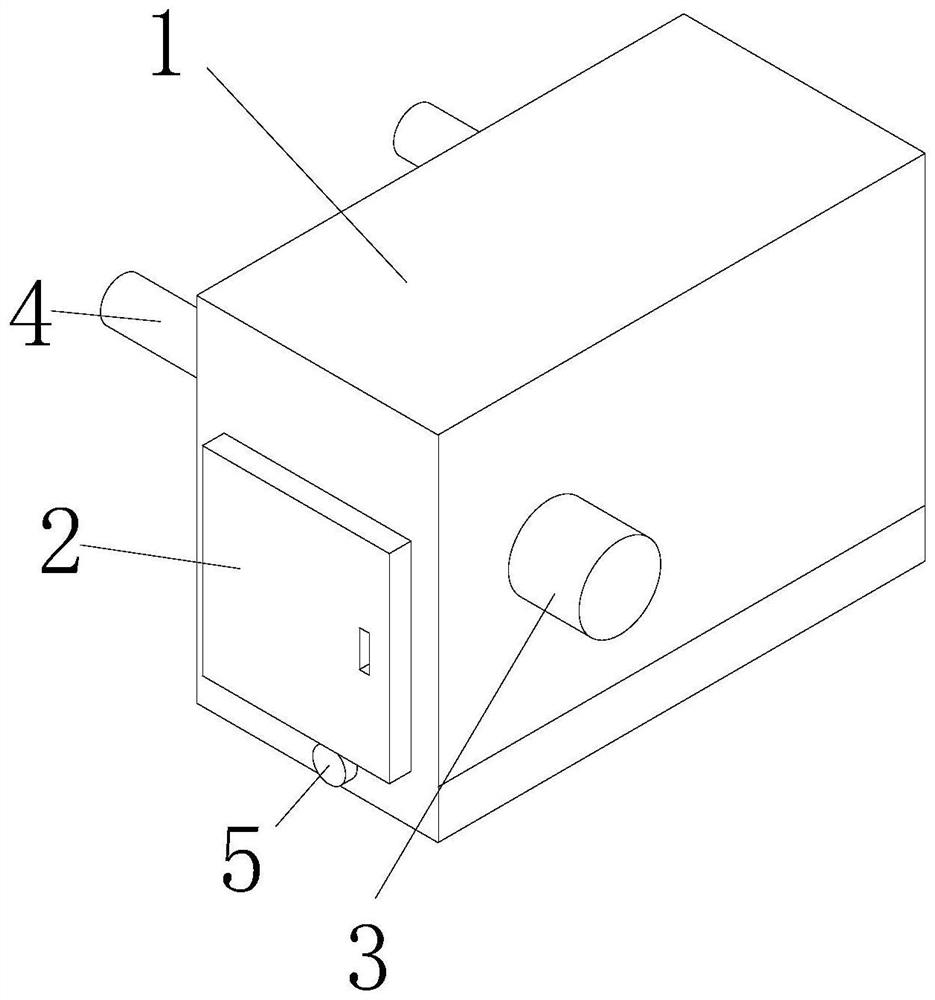
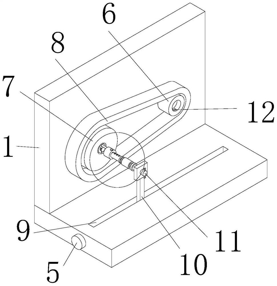
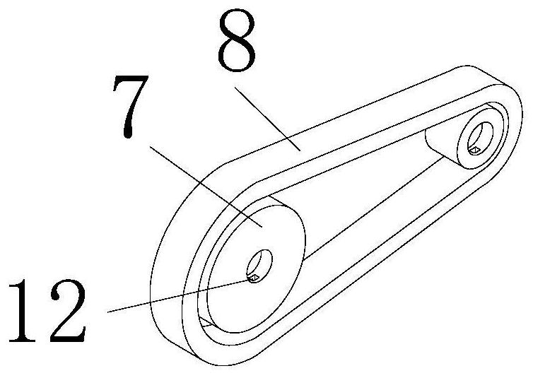
[0039] see Figure 1-8 , the present invention provides a technical solution: a kind of connection auxiliary equipment for driving pulley transmission, including a transmission box 1, a door panel 2 is arranged on the front surface of the transmission box 1, a motor 3 is fixedly connected to the right surface of the transmission box 1, and the transmission The front and rear sides of the left surface of the box 1 are rotatably connected with transmission shafts 4, and the right ends of the two transmission shafts 4 run through the transmission box 1 and extend to the inside of the transmission box 1, and the left surface of the transmission box 1 is rotatably connected with a small pulley 6 and large pulley 7, small pulley 6 and large pulley 7 are respectively located at the front and rear sides of the inner right surface of transmission case 1, and the left ends of two drive shafts 4 are fixedly connected with small pulley 6 and large pulley 7 respectively, small pulley 6 and ...

Embodiment 2

[0043] see Figure 1-8 , on the basis of Embodiment 1, the connection device includes a hollow fixed block 23, the fixed block 23 is arranged inside the transmission box 1, the right surface of the fixed block 23 is fixedly connected with a fixed rod 22, and the right end of the fixed rod 22 is fixedly connected There is a connecting sleeve 20 which is hollow inside, and the inside of the connecting sleeve 20 is slidingly connected with an adjusting rod 18, and the right end of the adjusting rod 18 extends out of the connecting sleeve 20, and the opposite ends of the adjusting rod 18 and the connecting rod 11 are fixedly connected with mutually compatible bolts Rod 17, two bolt rods 17 are threaded with bolt sleeves 16, the adjusting rod 18 and the connecting rod 11 are fixedly sleeved with limit rings 15, and the two limit rings 15 are respectively located on the left and right sides of the bolt sleeves 16;

[0044] Further, the top surface of the adjusting rod 18 is arranged...

Embodiment 3

[0046] see Figure 1-8 , on the basis of Embodiment 1 and Embodiment 2, the fixing device includes a rotating shaft 24, the rotating shaft 24 is rotatably connected to the right surface of the fixed block 23, and the outer wall of the rotating shaft 24 is fixedly connected with a protrusion 25, and the setting of the protrusion 25 can It is more convenient to rotate the rotating shaft 24, the left end of the rotating shaft 24 runs through the fixed block 23 and extends to the inside of the fixed block 23, the left end of the rotating shaft 24 is fixedly connected with a rotating rod 27, and the upper and lower ends of the rotating rod 27 are fixedly connected with a cam 28, two The opposite end of the cam 28 is provided with an arc-shaped connecting plate 29, and the two cams 28 are respectively in contact with the two connecting plates 29, and the opposite sides of the two connecting plates 29 are fixedly connected with two springs 30, and the two springs The opposite ends of...


PUM


Abstract

The invention discloses connection auxiliary equipment for transmission with a driving belt pulley, and relates to the technical field of driving belt pulleys. The connection auxiliary equipment for transmission with the driving belt pulley comprises a transmission box, wherein a door plate is arranged on the front surface of the transmission box, transmission shafts are rotationally connected to the front side and the rear side of the left surface of the transmission box, and a small belt pulley and a large belt pulley are rotationally connected to the left surface in the transmission box; and the left ends of the two transmission shafts are fixedly connected with the small belt pulley and the large belt pulley correspondingly, the small belt pulley and the large belt pulley are sleeved with a transmission belt, clamping grooves are formed in the upper surface and the lower surface in the small belt pulley and the large belt pulley, a connecting device is arranged in the transmission box, and a fixing device is arranged in the transmission box. Through the arrangement of the connecting device, the driven and driving relation between the large belt pulley and the small belt pulley can be easily adjusted, the adjusting process and steps can be simplified, the adjusting trouble degree is reduced, and the convenience of the device is improved.

Description

technical field [0001] The invention relates to the technical field of driving pulleys, in particular to an auxiliary device for connection with driving pulleys. Background technique [0002] Pulleys, which belong to disc and hub parts, are generally relatively large in size, and the manufacturing process is generally based on casting and forging. Generally, the larger size is designed by casting method, and the material is generally cast iron (good casting performance), and cast steel is rarely used (steel has poor casting performance); generally smaller size can be designed as forging, and the material It is made of steel, and the pulley is mainly used for long-distance transmission of power, such as the output of small diesel engine power, agricultural vehicles, tractors, automobiles, mining machinery, machining equipment, textile machinery, packaging machinery, lathes, forging machines, some small horsepower motorcycles Vehicle power transmission, agricultural machinery...

Claims


Application Information

Patent Timeline
Patent Type & Authority Applications(China)
IPC IPC(8): F16H7/00F16H7/02F16H7/06F16H57/035
CPCF16H7/00F16H7/02F16H7/06F16H57/035Y02E10/72
Inventor 钱军华陈林英
Owner 湖州晨翼五金有限公司
Why Eureka
Try Eureka