A fishbone clock tree and its implementation method
An implementation method and clock technology, which is applied in instruments, climate sustainability, computing, etc., can solve problems such as channel wiring congestion, difficulty in timing convergence, and high power consumption of clock trees, so as to reduce buffer units, facilitate timing convergence, and reduce Effect of Chip Power Consumption
- Summary
- Abstract
- Description
- Claims
- Application Information
AI Technical Summary
Problems solved by technology
Method used
Image
Examples
Embodiment 1
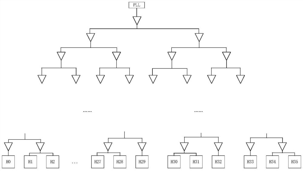
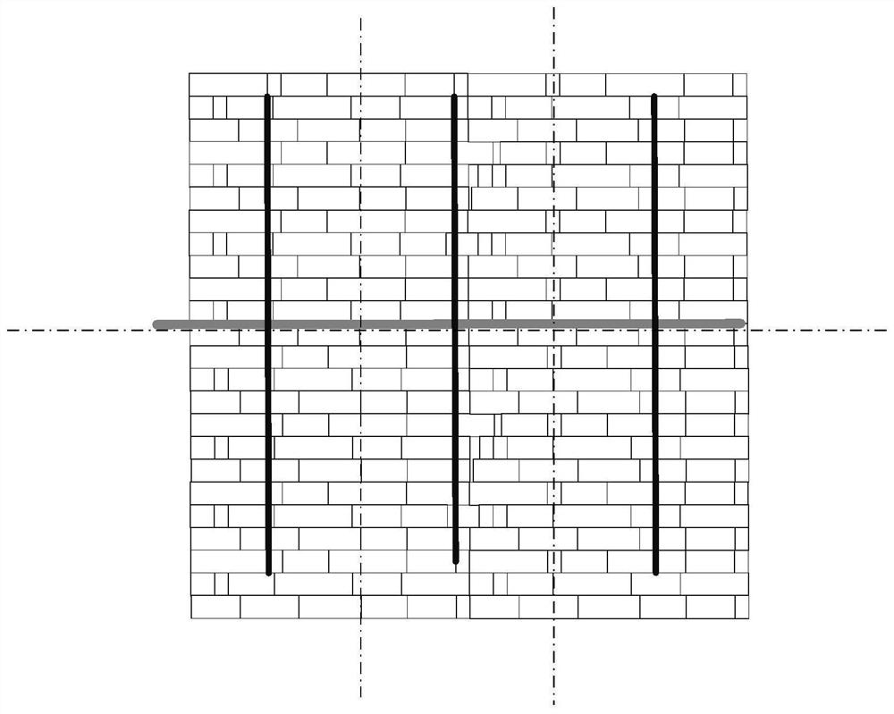
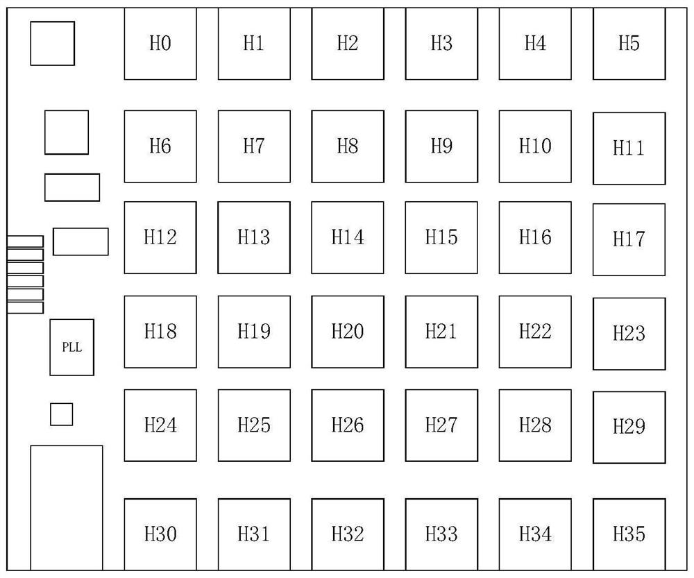
[0031] Refer to the attached figure 2 , attached Figure 4 and attached Figure 5 , the invention discloses a fishbone-shaped clock tree, comprising a main clock tree and several sub-clock trees, the main clock tree is drawn from the PLL, the sub-clock tree is drawn from the main clock tree, and the sub-clock tree is provided with A number of clock bifurcation points that serve as the source of the legacy clock tree to build the legacy clock tree.
[0032] In this embodiment, the master clock tree is arranged on the central axis of the chip. Set the main clock tree on the central axis of the chip or the center of multiple sub-modules of the chip, so that the sub-modules of the chip are distributed as evenly as possible on both sides of the main clock tree, which can reduce the length and wiring of the wiring from the physical distance. quantity. At the same time, when the main clock tree is located on the central axis of the chip, the sub-clock tree can also conveniently ...
Embodiment 2
[0039] The present invention also discloses a method for implementing a fishbone clock tree. The fishbone clock tree in Embodiment 1 is applied to a chip, which mainly includes the following steps:
[0040] Step 1. Obtain the sub-module layout of the chip.
[0041] Step 2. Lead out the main clock tree from the PLL of the chip and set the main clock tree according to the sub-module layout so that the main clock tree is located on the central axis of the chip.
[0042] Step 3. Lead out several sub-clock trees from the main clock tree, and distribute the sub-clock trees evenly on both sides of the main clock tree.
[0043] Step 4. The clock fork point is drawn from the sub-clock tree, and the traditional clock tree is established by using the clock fork point as the source of the traditional clock tree.
[0044] In step 1, since different chips are designed with different numbers of sub-modules, and the arrangement positions of these sub-modules are also different, the actual si...
Embodiment 3
[0053] On the basis of Example 2, refer to the appendix figure 2 , when the chip is a single-layer sub-module layout, the sub-clock tree derived from the main clock tree divides the chip into several sub-regions, and a traditional clock tree is established in each sub-region through the clock bifurcation points derived from the sub-clock tree.
PUM
 Abstract
Description
Claims
Application Information
 - R&D
- Intellectual Property
- Life Sciences
- Materials
- Tech Scout
- Unparalleled Data Quality
- Higher Quality Content
- 60% Fewer Hallucinations
Browse by: Latest US Patents, China's latest patents, Technical Efficacy Thesaurus, Application Domain, Technology Topic, Popular Technical Reports.
© 2025 PatSnap. All rights reserved.Legal|Privacy policy|Modern Slavery Act Transparency Statement|Sitemap|About US| Contact US: help@patsnap.com


