Ion trap radio frequency device
An ion trap and radio frequency signal technology, applied in the field of quantum computing, can solve the problems of many noise signals, many logic control units, and reduced ion capture time, so as to reduce noise signals, ensure stability, and improve the effect of time duration
- Summary
- Abstract
- Description
- Claims
- Application Information
AI Technical Summary
Problems solved by technology
Method used
Image

Examples
Embodiment 1
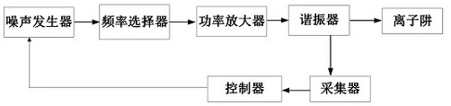
[0034] Such as figure 2 As shown, the ion trap radio frequency device provided by the embodiment of the present invention includes a noise generator, a frequency selector, a power amplifier, a resonator, a collector, and a controller, wherein:
[0035] The noise generator is used to prepare and output a white noise signal.
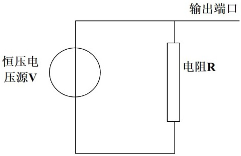
[0036] Specifically, such as image 3 As shown, the noise generator includes a resistor R and a constant voltage source V, wherein the resistance of the resistor R is 1M ohm, and the voltage of the constant voltage source V is 5V. When the current passes through the resistor R, the noise generator generates a white noise signal.
[0037] A frequency selector is used to extract a radio frequency signal of a specific frequency from a white noise signal.
[0038] Among them, a 48MHz radio frequency signal is usually used to drive the ions in the ion trap, so the frequency selector needs to extract a radio frequency signal with a frequency of 48MHz from a ...
Embodiment 2
[0047] The controller includes a temperature extraction module and a temperature control module. in:
[0048] The temperature extraction module is used for real-time calculation of the power of the radio frequency signal output by the collector and according to the power, real-time calculation of the ambient temperature of the channel where the radio frequency signal is located;
[0049] The temperature control module is used to judge in real time whether the power of the radio frequency signal output by the resonator changes according to the ambient temperature of the channel where the radio frequency signal is located.
[0050] Among them, the ambient temperature of the channel where the radio frequency signal is located is proportional to the power of the radio frequency signal output by the resonator, that is, the greater the power of the radio frequency signal output by the resonator, the greater the ambient temperature of the channel where the radio frequency signal is l...
Embodiment 3
[0055] Specifically, such as Image 6 As shown, the input signal ui is a white noise signal. After the white noise signal is amplified by the transistor T, a 48MHz radio frequency signal is selected in the LC resonant circuit, and the radio frequency signal is output to finally obtain a 48MHz radio frequency signal.
[0056] As an optional embodiment of the present invention, the temperature control module is a temperature control box.
[0057] Among them, when the ambient temperature of the channel where the radio frequency signal is located changes, the radio frequency signal output by the resonator will also fluctuate when it reaches the ion trap, and at the same time, the radio frequency signal output by the collector will also fluctuate, and then the radio frequency signal is input to the temperature extraction module.
PUM
 Abstract
Description
Claims
Application Information
 - R&D
- Intellectual Property
- Life Sciences
- Materials
- Tech Scout
- Unparalleled Data Quality
- Higher Quality Content
- 60% Fewer Hallucinations
Browse by: Latest US Patents, China's latest patents, Technical Efficacy Thesaurus, Application Domain, Technology Topic, Popular Technical Reports.
© 2025 PatSnap. All rights reserved.Legal|Privacy policy|Modern Slavery Act Transparency Statement|Sitemap|About US| Contact US: help@patsnap.com