
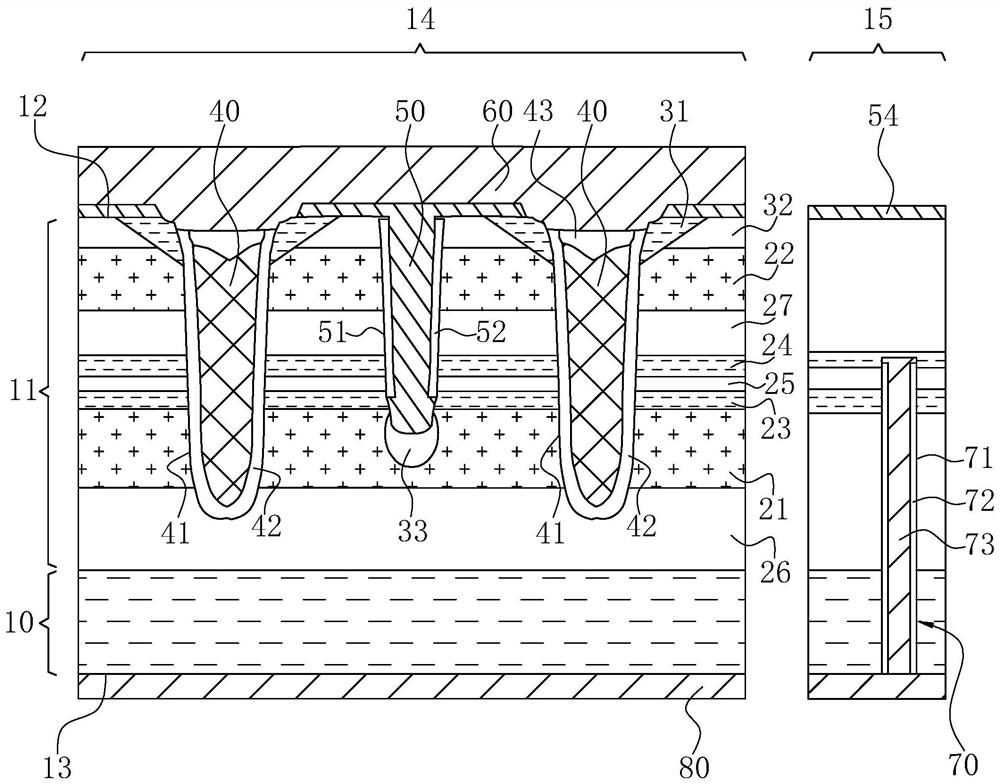
Chip structure and manufacturing method of multi-source MOS tube shared grid

A technology of MOS tube and chip structure, applied in semiconductor/solid-state device manufacturing, transistors, semiconductor devices, etc., can solve problems affecting electrical performance, increase MOS tube arrangement density, low process, etc. Enhanced ventilation performance and uniform heat distribution

Active Publication Date: 2022-04-26
深圳真茂佳半导体有限公司
View PDF12 Cites 0 Cited by
  • Summary
  • Abstract
  • Description
  • Claims
  • Application Information

AI Technical Summary

Problems solved by technology

[0008] The main purpose of the present invention is to provide a chip structure in which multi-source MOS transistors share the grid, which breaks the inherent thinking in this field, and double or multiple grooves can increase the arrangement density of MOS transistors and solve the problems caused by secondary grooves. The difference in groove depth affects the electrical performance, reducing the external technical constraints that require advanced micro-processing and precision photolithography machines for one groove
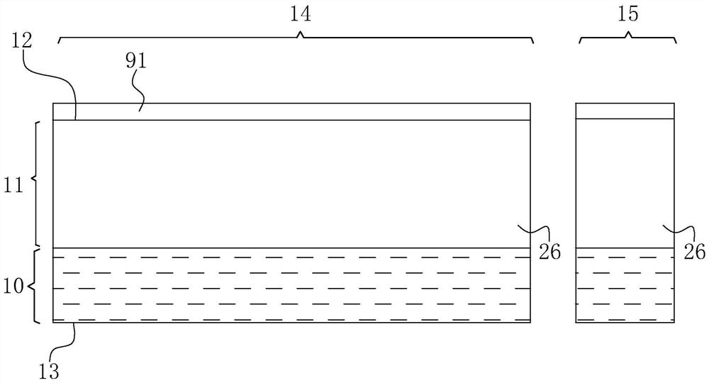
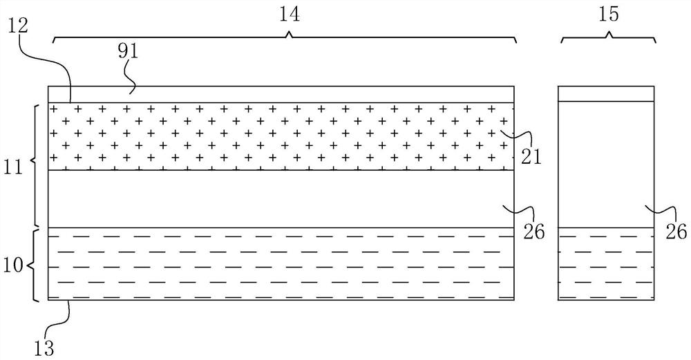
[0009] The second main purpose of the present invention is to provide a method for manufacturing a chip structure in which multi-source MOS transistors share a gate, so as to solve the influence of differences in groove depth in different processes when slotting twice or multiple times to improve the arrangement density of MOS transistors Due to the problem of electrical performance, products that originally required advanced micro-processes and precision photolithography machines can be produced equally with relatively low processes

Method used


Image

  • Chip structure and manufacturing method of multi-source MOS tube shared grid
  • Chip structure and manufacturing method of multi-source MOS tube shared grid
  • Chip structure and manufacturing method of multi-source MOS tube shared grid

Examples


Embodiment Construction

[0070] The technical solutions in the embodiments of the present invention will be clearly and completely described below in conjunction with the accompanying drawings in the embodiments of the present invention. Apparently, the described embodiments are only part of the embodiments for understanding the inventive concepts of the present invention, and cannot represent All the embodiments are not explained as the only embodiment. Based on the embodiments of the present invention, all other embodiments obtained by persons of ordinary skill in the art on the premise of understanding the inventive concepts of the present invention fall within the protection scope of the present invention.

[0071] It should be noted that if there is a directional indication (such as up, down, left, right, front, back...) in the embodiment of the present invention, the directional indication is only used to explain the relationship between the components in a certain posture. If the specific postu...


PUM


Abstract

The invention relates to a chip structure and a manufacturing method of a multi-source MOS transistor sharing a gate. The structure includes a drain substrate, a gate filling body, a source filling body located between the gate filling bodies, and a drain substrate. The source capping layer and the semiconducting hole structure provided on the backside of the drain substrate. The source cover layer is driven by the first height segment of the gate filling body to conduct through the second active layer to the back of the semiconducting hole structure and the drain substrate to form the first MOS transistor structure; the source filling body accepts The second height segment of the gate filling body is driven to conduct to the back side of the drain substrate through the first active layer, so as to form a second MOS transistor structure. The field effect transistor structure provided by the present invention has the effect of sharing the gate of multi-source MOS transistors to realize the densification of MOS devices and not being affected by the electrical performance due to the difference in trench depth due to secondary trenching.

Description

technical field [0001] The invention relates to the technical field of semiconductor transistors, in particular to a chip structure and a manufacturing method of a multi-source MOS transistor sharing a gate. Background technique [0002] Field-effect transistors are generally arranged in a semiconductor chip. In order to increase the number of MOS transistors within the limited area of ​​the chip, more and more gates need to be arranged and the gate structure is vertical, which makes the transistor structure dense. Therefore, the gate structure It needs to be erected on the working surface of the wafer processing or buried in the working surface. For the embedded gate, the gate trench requires two or more staggered grooves on the wafer surface during the manufacturing process. Then, it is difficult to control all the gate trenches to be at the same trench depth when the trenches are performed in different processes. When the previously formed trenches and the later formed t...

Claims


Application Information

Patent Timeline
Patent Type & Authority Patents(China)
IPC IPC(8): H01L29/78H01L29/06H01L27/088H01L21/336
CPCH01L29/7813H01L29/7831H01L29/0603H01L29/0684H01L29/66484H01L29/66727H01L29/66734H01L27/088
Inventor 任炜强春山正光
Owner 深圳真茂佳半导体有限公司
Learn More