Supercharge Your Innovation With Domain-Expert AI Agents!

Driving circuit of piezoelectric actuator and charge driving method

A piezoelectric driver and drive circuit technology, applied in piezoelectric effect/electrostrictive or magnetostrictive motors, generators/motors, electrical components, etc., can solve the difficulties in the application of piezoelectric materials, errors in current measurement values, Errors and other issues, to achieve the effect of convenient implementation, avoiding errors, and easy realization

Pending Publication Date: 2021-11-30
YANCHENG INST OF TECH
View PDF0 Cites 0 Cited by
  • Summary
  • Abstract
  • Description
  • Claims
  • Application Information

AI Technical Summary

Problems solved by technology

[0003] Due to the hysteresis and nonlinearity of the piezoelectric material itself, and in the process of measuring the current, there will be errors in the measured value of the current, and in the process of integration, it will cause the accumulation of errors, which will bring certain difficulties to the application of piezoelectric materials, so it is urgently needed A driving circuit and charge driving method of a piezoelectric driver to solve the above problems

Method used


Image

  • Driving circuit of piezoelectric actuator and charge driving method
  • Driving circuit of piezoelectric actuator and charge driving method
  • Driving circuit of piezoelectric actuator and charge driving method

Examples


Embodiment

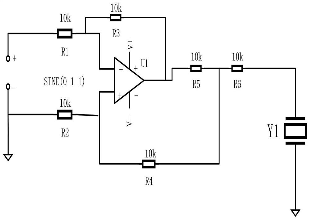
[0022] Embodiment: a driving circuit of a piezoelectric driver, including a power supply circuit, a driving circuit and a control circuit, the power supply circuit outputs a specified sinusoidal voltage, and the driving circuit includes an operational amplifier, which receives the voltage output by the power supply circuit and amplifies the voltage to generate a driving voltage. The signal is transmitted to the control circuit, and the control circuit receives the output voltage of the operational amplifier, and forms a loop with the power supply, and at the same time detects the overall operation of the circuit and feeds it back to the input terminal.

[0023] refer to figure 1 , the power supply circuit includes a power supply V1, a resistor R1 and a resistor R2, the driving circuit includes an operational amplifier U1, and the control includes a piezoelectric driver Y1, a resistor R3, a resistor R4, a resistor R5 and a resistor R6, wherein the positive pole of the power supp...


PUM


Abstract

The invention discloses a driving circuit of a piezoelectric actuator and a charge driving method. The driving circuit comprises a power supply circuit, a driving circuit and a control circuit. The method comprises the steps that the power supply circuit generates a driving signal, and the driving signal is amplified by an operational amplifier; the piezoelectric actuator starts to work after receiving a driving signal, and can calculate the magnitude of charges on the piezoelectric element according to the magnitude of the input voltage in combination with a formula, and achieves the accurate control over the displacement distance of the piezoelectric actuator through the charges. Based on the principle that the hysteresis between the input charge and the output displacement of the piezoelectric actuator is obviously smaller than the hysteresis between the input voltage and the displacement, the piezoelectric hysteresis effect can be effectively reduced; meanwhile, the voltage or current on the piezoelectric element does not need to be measured, errors caused by measurement are avoided, and the circuit is simple in structure, easy to implement and convenient to implement.

Description

technical field [0001] The invention relates to the technical field, in particular to a driving circuit and a charge driving method of a piezoelectric driver. Background technique [0002] A piezoelectric actuator is a new type of actuator that uses the inverse piezoelectric effect of piezoelectric materials to convert electrical energy into mechanical energy. Piezoelectric actuators have the advantages of small size, fast response, no need for lubrication and deceleration devices, high resolution, large thrust, no electromagnetic interference, and self-locking when power is off. It is a micro-displacement output device widely used in the field of precision drives. It has broad application prospects in the fields of ultra-precision machining, micro-nano manufacturing, microelectronics manufacturing, aerospace, biological operations and robot joints. [0003] Due to the hysteresis and nonlinearity of the piezoelectric material itself, and in the process of measuring the curr...

Claims


Application Information

Patent Timeline
IPC IPC(8): H02N2/06
CPCH02N2/062
Inventor 郑雷童立琛陈远晟韦文东董香龙陈玉航万俊豪聂承敏
Owner YANCHENG INST OF TECH
Features
  • R&D
  • Intellectual Property
  • Life Sciences
  • Materials
  • Tech Scout
  • Unparalleled Data Quality
  • Higher Quality Content
  • 60% Fewer Hallucinations
Learn More