Phase-locked loop circuit reference stray elimination method, elimination device and phase-locked loop system

A phase-locked loop and circuit technology, applied in the field of circuits, can solve problems such as failure, improvement of reference stray elimination effect, difficulty in obtaining definite and quantitative effects, etc., to achieve the effect of expanding the frequency band bandwidth and improving the elimination effect

Active Publication Date: 2021-11-30
上海聆芯科技有限公司
View PDF11 Cites 4 Cited by
  • Summary
  • Abstract
  • Description
  • Claims
  • Application Information

AI Technical Summary

Problems solved by technology

[0003] The existing methods for eliminating reference spurs of phase-locked loops all belong to reducing the influence of reference spurs from the source on fixed-frequency reference signals, but it is difficult to obtain definite and quantitative effects in practical applications
In addition, even if a good spur elimination effect is obtained for a reference signal with a fixed frequency, if the reference signal frequency changes, the matched electrical parameter values ​​may be completely invalid, and the reference spur elimination effect is more difficult to determine, so the reference spur Elimination effect needs to be improved

Method used


Image

  • Phase-locked loop circuit reference stray elimination method, elimination device and phase-locked loop system
  • Phase-locked loop circuit reference stray elimination method, elimination device and phase-locked loop system
  • Phase-locked loop circuit reference stray elimination method, elimination device and phase-locked loop system

Examples


Embodiment Construction

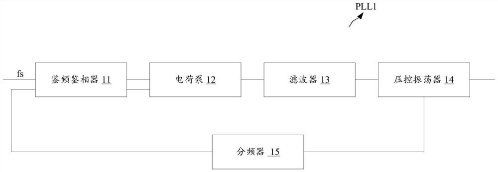
[0058] Such as figure 1 The schematic diagram of the structure of the charge pump phase-locked loop circuit shown, the phase-locked loop PLL1 includes a frequency detector 11, a charge pump 12, a filter 13, a voltage-controlled oscillator 14 and a frequency divider 15, wherein, by the voltage The controlled oscillator 14 generates a clock signal, and after the frequency division by the frequency divider 15, the frequency division signal is obtained and fed back to the frequency and phase detector 11, and the frequency division signal and the reference signal are divided by the frequency and phase detector 11 The frequency fs and the phase are compared, and the comparison result is filtered by the charge pump 12 and the filter 13 and then output to the voltage-controlled oscillator 14 for frequency control.

[0059] The key performance parameters of the phase-locked loop include phase noise, unwanted by-products or spurious frequencies in the frequency synthesis process (referr...


PUM


Abstract

A phase-locked loop circuit reference stray elimination method, elimination device and phase-locked loop system are disclosed; wherein the phase-locked loop circuit comprises a phase frequency detector, a loop filter and a voltage-controlled oscillator which are sequentially coupled, the elimination device comprises a frequency detection unit, a controller and a notch filter, wherein the frequency detection unit is suitable for detecting real-time reference frequency input to the phase frequency detector to obtain a reference frequency detection value; the controller is suitable for obtaining a reference frequency reference value, obtaining a control parameter adjustment value corresponding to the notch filter according to the reference frequency reference value and the reference frequency detection value, and adjusting an electrical parameter value of the notch filter according to the control parameter adjustment value, thereby enabling the center frequency value of the notch filter to be the same as the reference frequency detection value; and the notch filter is arranged between the loop filter and the voltage-controlled oscillator, and the electrical parameter value of the notch filter is adjustable. According to the scheme, the reference stray elimination effect can be improved.

Description

technical field [0001] The embodiments of the present invention relate to the field of circuit technology, and in particular to a phase-locked loop circuit reference spur elimination method, an elimination device, and a phase-locked loop system. Background technique [0002] The phase-locked loop is a circuit that provides a local reference clock for the communication system circuit, and realizes the frequency multiplication from the reference frequency to the final output frequency. The most common spur in a PLL is the reference spur. These spurious signals can be amplified by charge pump source and sink current mismatches, charge pump leakage currents, and insufficient power supply decoupling. In wireless receiver designs, spurious signals can mix with other interfering signals to generate useful signals, desensitizing the receiver. Therefore, eliminating or reducing reference spurs is of great significance to the performance of wireless communication systems. [0003] ...

Claims


Application Information

Patent Timeline
Patent Type & Authority Applications(China)
IPC IPC(8): H03L7/085H03L7/093H03L7/18
CPCH03L7/085H03L7/093H03L7/18Y02D30/70
Inventor 施晓阳
Owner 上海聆芯科技有限公司
Why Eureka
Try Eureka