Antenna interface unit test method and device, terminal and readable storage medium
A unit test and antenna interface technology, applied in the detection field, can solve the problems of low accuracy of the detection data results of the antenna interface unit, performance detection of the antenna interface unit, etc., and achieve the effect of reducing technology dependence
- Summary
- Abstract
- Description
- Claims
- Application Information
AI Technical Summary
Problems solved by technology
Method used
Image
Examples
Embodiment 1
[0040] A method for testing an antenna interface unit, comprising the steps of:
[0041] The first step is to obtain the standard test process; the standard test process includes test items, test equipment, test environment, and standard data. Among them, the required test equipment, test environment, and standard data are determined through the required test items, and the test principle is generated Connection block diagram and test wiring diagram;
[0042] Wherein, the test principle connection block diagram includes a plurality of test devices, and the test connection diagram includes the wiring modes between each test device.
[0043] After confirming the test equipment, test principle connection block diagram and measurement connection diagram, the user can build the test environment according to the drawings through manual connection.
[0044] At the same time, it is also possible to connect multiple test equipment in advance, and then install the corresponding switch ...
Embodiment 2
[0056] For the method in Embodiment 1, this embodiment provides a specific structure.
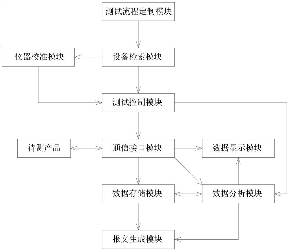
[0057] A testing device for an antenna interface unit includes a test flow customization module, a test control module, a communication interface module, a data analysis module and a message generation module.
[0058] The test process customization module is used to obtain the standard test process, and the standard test process is a preset process or an on-site development process;
[0059] A plurality of standard test procedures are stored in the test procedure customization module, and the standard test procedure may be a procedure preset in advance, and it only needs to be called when testing.
[0060]It can also be a standard test process input on site, that is, the process that needs to be measured has not been preset. You can enter the corresponding standard test process when testing for the first time and save it as a preset process. When you measure next time, That is, the call c...
Embodiment 3
[0071] This embodiment is an optimization for Embodiment 1, that is, the test environment is determined before outputting control instructions to the product to be tested;
[0072] The test environment is whether the direct connection relationship between various test equipment and the product under test is correct, whether the test equipment is working normally, etc.
[0073] Obtain the relevant information of the online test equipment (including but not limited to the equipment name, model, VISA address or IP address), and compare it with the test equipment information in the standard test process to determine whether the test environment matches, if not, stop the test process , and give an alarm.
[0074] The specific method steps are:
[0075] The first step is to obtain the standard testing process;
[0076] The second step is to obtain the relevant information of the online test equipment, and compare it with the test equipment information in the standard test process ...
PUM
 Abstract
Description
Claims
Application Information
 - R&D
- Intellectual Property
- Life Sciences
- Materials
- Tech Scout
- Unparalleled Data Quality
- Higher Quality Content
- 60% Fewer Hallucinations
Browse by: Latest US Patents, China's latest patents, Technical Efficacy Thesaurus, Application Domain, Technology Topic, Popular Technical Reports.
© 2025 PatSnap. All rights reserved.Legal|Privacy policy|Modern Slavery Act Transparency Statement|Sitemap|About US| Contact US: help@patsnap.com

