Liquid-slag separation device for paint spraying wastewater

A technology for separation of liquid and slag and waste water, which is used in grease/oily substance/float removal devices, water aeration, water/sewage treatment, etc. Extraction and other problems to achieve the effect of reducing energy consumption, reducing cost and difficulty, and improving efficiency

Active Publication Date: 2021-12-03
莱阳市春帆漆业有限责任公司
View PDF7 Cites 0 Cited by
  • Summary
  • Abstract
  • Description
  • Claims
  • Application Information

AI Technical Summary

Problems solved by technology

[0004] The purpose of the present invention is to solve the problem of inhomogeneous mixing of liquid medicine and waste water in the prior art. The low mixing speed leads to insufficient reaction of harmful substances and cannot be completely extracted, and some impurities in the paint-containing waste water will settle at the bottom. Impurities need to rely on the shortcomings of manual regular cleaning, and a liquid slag separation device for paint spraying wastewater is proposed

Method used


Image

  • Liquid-slag separation device for paint spraying wastewater
  • Liquid-slag separation device for paint spraying wastewater
  • Liquid-slag separation device for paint spraying wastewater

Examples


Embodiment 1

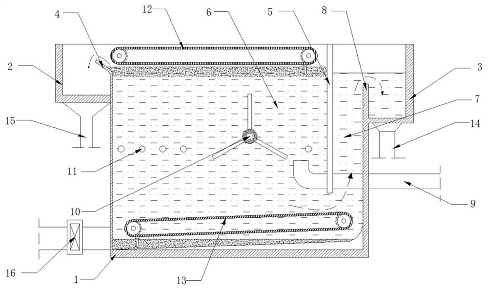
[0037] refer to Figure 1-2, a liquid slag separation device for paint spraying wastewater, comprising a device box 1, one end of the device box 1 is provided with a sewage tank 2, the other end is provided with a drainage box 3, and the end of the device box 1 close to the drainage box 3 A partition 5 is fixedly arranged, and a drainage gap is reserved between the bottom of the partition 5 and the bottom of the device box 1. The side of the partition 5 close to the drainage tank 3 forms a drainage channel 7, and the other side forms a reaction pool 6. A baffle 8 is arranged between the drainage channel 7 and the drainage box 3, and an arc-shaped plate 4 is arranged between the reaction pool 6 and the sewage box 2;

[0038] refer to figure 1 , 2 And 5, the device box 1 is located at the position below the drainage tank 3 and is equipped with a paint waste water pipe 9 extending to the inner cavity of the reaction tank 6. In the reaction tank 6, a mixing mechanism 10 is insta...

Embodiment 2

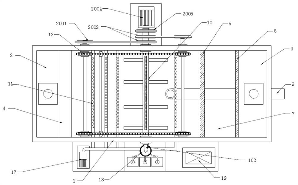
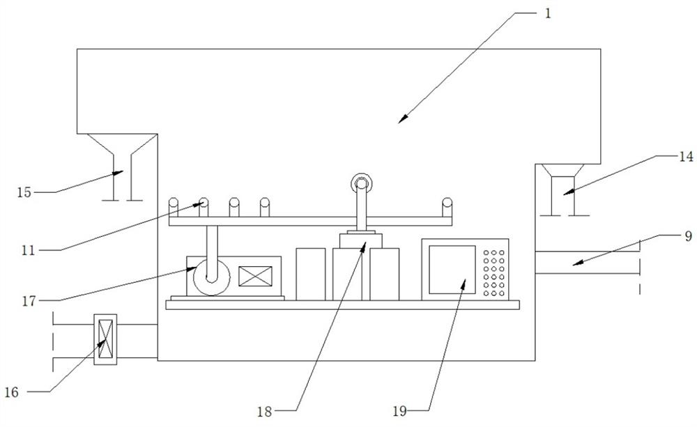
[0052] refer to Figure 7-10 The difference between this embodiment and Embodiment 1 is that the structure of the mixing mechanism 10 and the driving system 20 is different. In this embodiment, the mixing mechanism 10 is a floating structure, which includes a floating plate 106, a mixing paddle 113 and a linkage mechanism. The plate 106 is arranged in the reaction tank 6 and the two ends of the floating plate 106 are respectively provided with limit sliders 112, and the inner walls of both sides of the reaction tank 6 are longitudinally provided with limit chutes 21 matching the limit sliders 112, The limit slider 112 is slidably installed in the limit chute 21, and one end of the floating plate 106 is provided with a slide bar 107 along its width direction, and the slide bar 107 is provided with a movable groove 108 along its length direction, and the linkage mechanism includes a rotating shaft 111, Connecting rod 110 and rotating slider 109, rotating shaft 111 is installed o...


PUM


Abstract

The invention discloses a liquid-slag separation device for paint spraying wastewater, and relates to the field of solid-liquid treatment. In order to solve the problems that harmful substances cannot be completely extracted due to low mixing speed of existing liquid medicine and wastewater, and impurities can settle at the bottom and need to be manually cleaned regularly, the invention provides the following scheme: the liquid-slag separation device comprises a box body; a sewage discharge box is arranged at one end of the device box body, and a drainage box is arranged at the other end of the device box body; a partition plate is fixedly arranged at the end, close to the drainage box, in the device box body; a drainage notch is reserved between the bottom of the partition plate and the bottom of the device box body; and a drainage channel is formed in the side, close to the drainage box, of the partition plate, and a reaction tank is formed in the other side of the partition plate. Through the mixing mechanism and the aeration pipe, the mixing rate of liquid medicine and waste water is increased, and the waste residue separation efficiency is improved; the suspension deslagging device and the sediment discharging device are respectively used for removing suspended matters and sediments; and the driving system drives the mixing mechanism, the suspension deslagging device and the sediment discharging device to operate at the same time, and energy conservation and environment protection are achieved.

Description

technical field [0001] The invention relates to the field of solid-liquid treatment, in particular to a liquid slag separation device for paint spraying wastewater. Background technique [0002] The Chinese patent with the application number CN201220155557.9: a paint slag separation tank device (public number: CN202609997U; authorization announcement date: December 19, 2012) discloses: It is composed of a sloping plate and an overflow tank. There is a slag discharge sloping plate on one side of the slot on the tank body, an overflow tank is provided on the opposite side of the slag discharge sloping plate, and a partition plate is provided in the tank body. The partition plate will The tank body is divided into two tanks, the paint slag tank and the clear night tank. The bottom of the paint slag tank and the clear night tank are connected. There is a water inlet pipe on the side wall of the tank body. There are two water outlets horizontally on the water inlet pipe. The wat...

Claims


Application Information

Patent Timeline
Patent Type & Authority Applications(China)
IPC IPC(8): C02F9/04
CPCC02F7/00C02F1/40C02F2001/007C02F2201/002
Inventor 毕克举刘彦澎解宗桥刘玮
Owner 莱阳市春帆漆业有限责任公司
Why Eureka
Try Eureka