
Core material, blade and blade forming method

A molding method and core material technology, applied to machines/engines, other household appliances, mechanical equipment, etc., can solve problems such as poor surface quality and strength of structural parts, large differences in penetration speed, waste of raw materials, etc., to avoid waste of resin Raw materials, improving fixed adhesive performance, and avoiding the effect of residual resin

Pending Publication Date: 2021-12-03
SHANGHAI ELECTRIC WIND POWER GRP CO LTD
View PDF8 Cites 0 Cited by
  • Summary
  • Abstract
  • Description
  • Claims
  • Application Information

AI Technical Summary

Problems solved by technology

[0003] At present, there are two types of core material structures: first, shallow grooves are set on the upper and lower surfaces of the core material at a certain distance, and holes are drilled in the thickness direction. The resin content of the core material in this processing method is less, which is difficult to meet the structural strength requirements, and the core material The material cannot be bent during the laying process, and can only be used for plane production, and its application is limited. Holes are drilled at fixed intervals, and the core material is bonded and fixed together with composite felt on the lower surface. This core material can be laid in a curved surface cavity, but it needs to lay a diversion net, and the resin content in the groove is relatively high. , the waste of raw materials is serious, and the glue flow and penetration speed on the upper and lower surfaces of the core material are quite different in this processing method. Spots, resulting in poor quality and strength of the surface of structural parts

Method used


Image

  • Core material, blade and blade forming method
  • Core material, blade and blade forming method
  • Core material, blade and blade forming method

Examples


Embodiment Construction

[0054] The present invention is further illustrated below by means of examples, but the present invention is not limited to the scope of the examples.

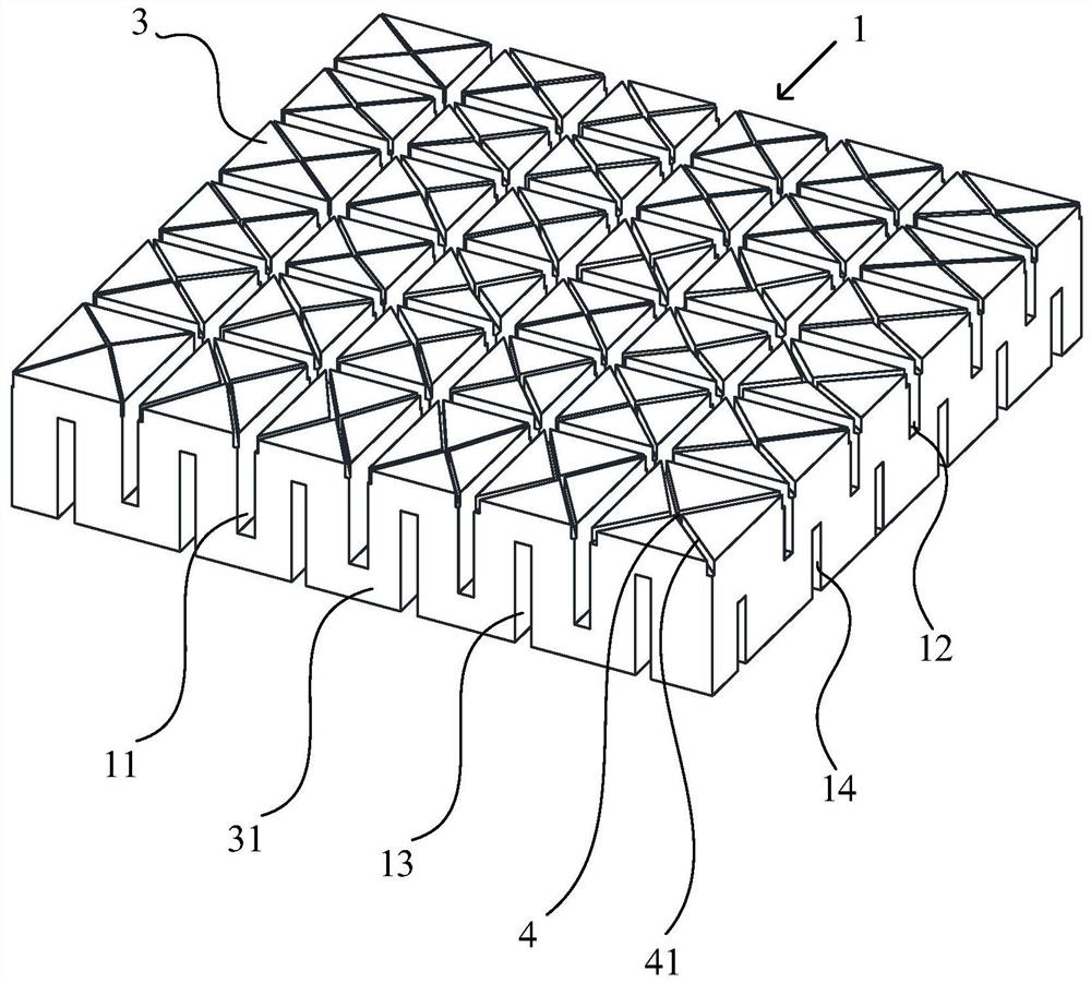
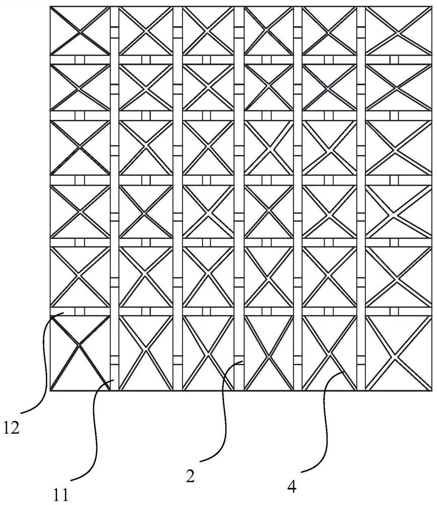
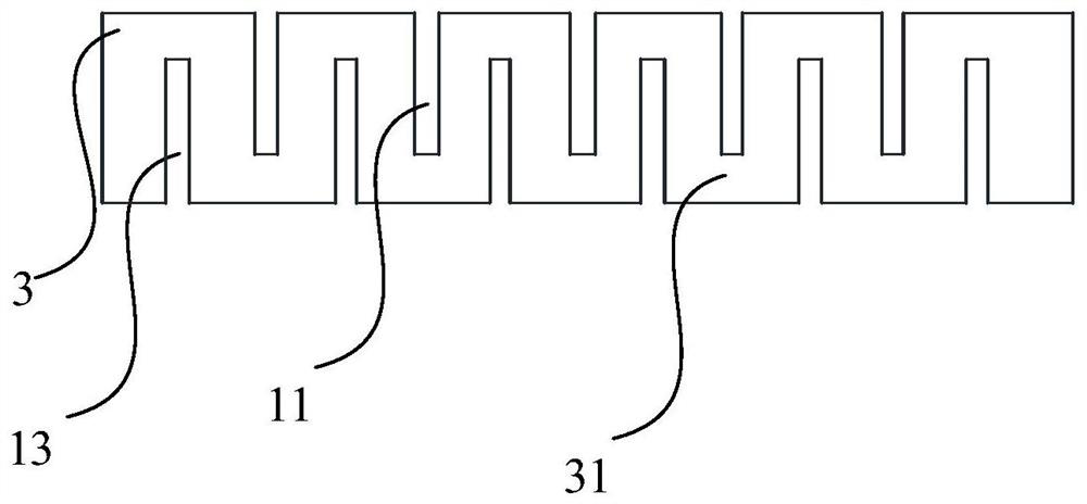
[0055] Such as Figure 1-4As shown, a core material 1, the upper surface of the core material 1 is provided with at least one first deep groove 11 and at least one first shallow groove 12 connected to each other, and the first deep groove 11 and the first shallow groove 12 are arranged on the upper surface. Different directions of the surface and extending to the edge of the upper surface, the lower surface of the core material 1 is provided with at least one second deep groove 13 and at least one second shallow groove 14 that communicate with each other, and the second deep groove 13 and the second shallow groove 14 are arranged on the lower surface. Different directions of the surface and extending to the edge of the lower surface, the depth of the first deep groove 11 and the second deep groove 13 is 1 / 3 to 4 / 5 of the thick...


PUM


Abstract

The invention discloses a core material, a blade and a blade forming method. At least one first deep groove and at least one first shallow groove which are in communication with each other are formed in the upper surface of the core material, the first deep grooves and the first shallow grooves are formed in different directions of the upper surface and extend to the edge of the upper surface, the lower surface of the core material is provided with at least one second deep groove and at least one second shallow groove which are in communication with each other, the second deep grooves and the second shallow grooves are arranged in different directions of the lower surface and extend to the edge of the lower surface, the depth of the first deep grooves and the depth of the second deep grooves are 1 / 3-4 / 5 of the thickness of the core material, and the depth of the first shallow grooves and the depth of the second shallow grooves are smaller than those of the first deep grooves and the second deep grooves. The grooves are formed in the upper surface and the lower surface of the core material in different directions, so that the resin infiltration capacity of the core material is improved, the fixing and bonding performance of the core material and reinforced fibers is improved, the resin content in the core material can be improved, waste of resin raw materials can be avoided, the core material in the scheme is good in flow guide effect, and meanwhile the core material can be freely bent.

Description

technical field [0001] The invention relates to the field of fan blades, in particular to a core material, a blade and a molding method of the blade. Background technique [0002] The core material is one of the key materials for wind power blades. The sandwich structure can be used to manufacture large composite components, such as wind power blades / ships / aircraft and other components. Usually, the structure is reinforced fiber-wrapped sandwich structure core material, that is, the upper surface of the core material and The lower surface is made of reinforcing fibers. In the production process, vacuum infusion molding is usually used, that is, the resin is injected into the reinforcing fibers from the outside under a certain negative pressure in the system, and then cured and formed. The structure of the core material has a great influence on the flow of the resin. It has a certain influence on the performance, the wetting effect of the reinforcing fiber and the stability o...

Claims


Application Information

Patent Timeline
IPC IPC(8): F03D80/00B29C70/34B29L31/08
CPCF03D80/00B29C70/342B29L2031/085F05B2280/6003F05B2280/6015Y02E10/72
Inventor 白宏伟齐志攀王国军
Owner SHANGHAI ELECTRIC WIND POWER GRP CO LTD
Learn More