Building material detection system and method

A detection system and technology for building materials, applied in the direction of analyzing materials, applying stable tension/pressure to test the strength of materials, measuring devices, etc., can solve the problems of reducing labor intensity, high labor intensity, hidden safety hazards, etc., to reduce labor Strength, avoiding potential safety hazards, and avoiding the effects of lateral offset

Pending Publication Date: 2021-12-03
郑州市建设工程质量检测有限公司
View PDF0 Cites 0 Cited by
  • Summary
  • Abstract
  • Description
  • Claims
  • Application Information

AI Technical Summary

Problems solved by technology

[0003] In order to ensure the accuracy of the realization, it is often necessary to conduct a large number of repeated tests on the same type of pipe. In the existing test process, it is often necessary to manually clamp the pipe, and then perform the pressure expansion process after the clamp is completed. The manual labor intensity Large, due to the need for manual operation, there are certain potential safety hazards
In order to compare the test data obtained from a variety of pipes with different outer diameter specifications, different wall thicknesses, and different materials, it is often necessary to test multiple sets of equipment suitable for different pipe specifications, resulting in high costs
[0004] Therefore, there is an urgent need for a detection system and method for building materials, which can realize the expansion test of pipes with different specifications, and does not need manual clamping of pipes, reducing labor intensity and reducing Safety hazards caused by manual clamping

Method used


Image

  • Building material detection system and method
  • Building material detection system and method
  • Building material detection system and method

Examples


Embodiment 1

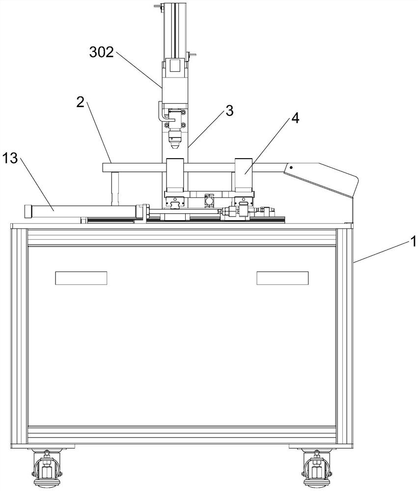
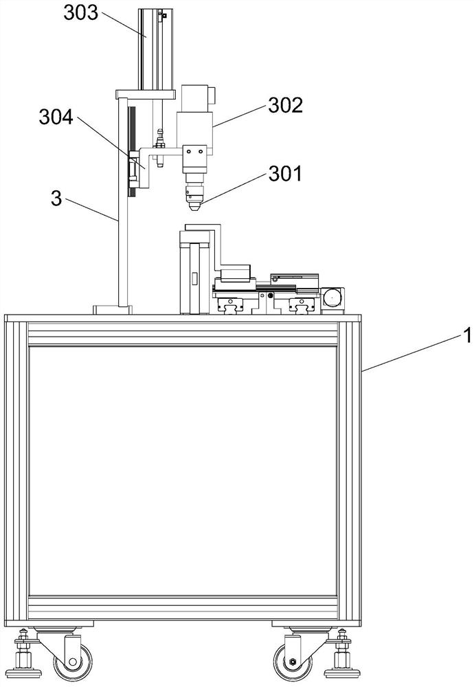
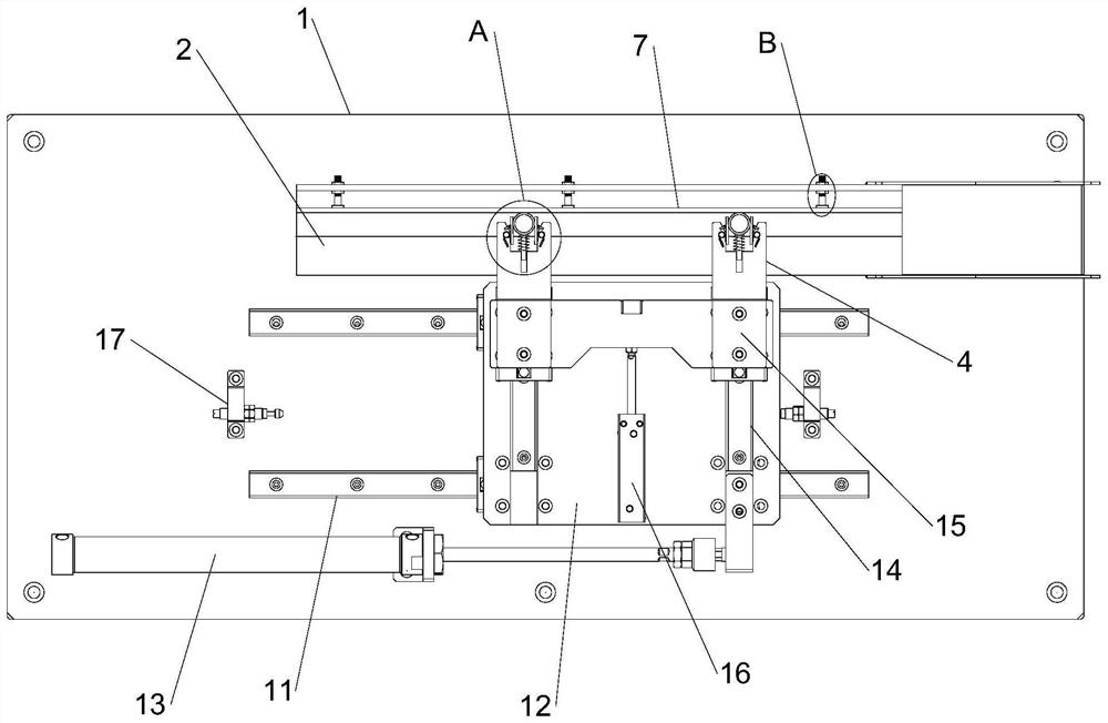
[0041] The detection system for building materials of the present invention comprises a placement platform 1, a workbench 2 is arranged above the placement platform 1, a support plate 3 is provided on the upper end of the placement platform 1, a detection air pump 302 is provided on the support plate 3, and a detection air pump 302 The lower end of the workbench 2 is provided with a detection probe 301 above the workbench 2. The lower end of the detection probe 301 is tapered, and the upper end of the workbench 2 is provided with a positioning groove 201. A vertically placed pipe 202 is arranged in the positioning groove 201. The workbench 2 The upper end is provided with a baffle plate 7 that can move along the relative positioning groove 201. The upper end of the workbench 2 is provided with a manipulator 4. The manipulator 4 is provided with an elastic holding assembly 5 for elastically holding the outer wall of the pipe material 202. The manipulator 4 and the baffle plate 7 ...

Embodiment 2

[0044] This embodiment is further optimized on the basis of Embodiment 1 as follows: the elastic holding assembly 5 includes two symmetrically arranged elastic holding units, and the elastic holding units include a holding plate 501, a positioning pin, a positioning cylinder 502, Positioning frame 503, positioning plate 506, torsion spring 505 and fixed pin 504; The side wall of manipulator 4 runs through and is provided with hold tight groove 401, and the two inwalls of hold tightly groove 401 are all provided with hold tight inclined-plane, between two hold tightly inclined-planes The distance between them increases gradually along the outward direction. The holding plate 501 is set in the holding groove 401. The positioning cylinder 502 is arranged on the holding plate 501 and is located on the side close to the holding slope. The positioning cylinder 502 runs through the positioning cylinder 502. , the two ends of the positioning cylinder 502 are connected to each other wit...

Embodiment 3

[0047] This embodiment is further optimized on the basis of Embodiment 1 as follows: the bottom wall of the holding groove 401 is also provided with a guide groove 6, a guide rod 601 is arranged in the guide groove 6, and a guide rod 601 is arranged on the upper end of the guide rod 601. The ejection plate 603 where the pipes 202 are in contact with each other, the guide rod 601 is covered with an ejection spring 602 , and the ejection spring 602 is located between the ejection plate 603 and the bottom wall of the holding groove 401 .

[0048] After adopting the above technical solution: by setting the guide rod 601 and the guide groove 6, during the process of tightening the pipe 202, the ejection spring 602 is further compressed. When the pipe 202 needs to be unloaded after the inspection is completed, the manipulator 4 drives the pipeline to slide within the positioning, and the baffle 7 is always in contact with the pipe 202 during the movement; The hindrance effect of the...


PUM


Abstract

The invention discloses a building material detection system and method, and relates to the technical field of building material detection. A workbench is arranged over a placing table, a supporting plate is arranged at the upper end of the placing table, a detection air pump is arranged on the supporting plate, a detection probe is arranged at the lower end of the detection air pump, the lower end of the detection probe is conical, a positioning groove is formed in the upper end of the workbench, a baffle capable of moving along the relative positioning groove is arranged at the upper end of the workbench, a manipulator is arranged at the upper end of the workbench and provided with an elastic holding assembly and a horizontal moving assembly, a through hole is formed in the bottom wall of the positioning groove in a penetrating mode, an elastic abutting assembly is arranged in the through hole, and a lifting moving assembly is arranged at the lower end of the elastic abutting assembly. According to the pipe orifice expansion test device, pipe orifice expansion tests can be carried out on pipes of different specifications, meanwhile, the pipes do not need to be clamped manually, the labor intensity of workers is reduced, and meanwhile potential safety hazards caused by manual clamping are reduced.

Description

technical field [0001] The invention relates to the technical field of building material detection, in particular to a detection system and method for building materials. Background technique [0002] Building materials can be divided into structural materials, decorative materials and some special materials. The structural materials include wood, bamboo, stone, cement, concrete, metal, brick, ceramics, glass, engineering plastics and composite materials. In the process of manufacturing pipes, in order to test different materials, different wall thicknesses of pipes or pipes with different outer diameters, when the nozzle of the pipe is subjected to expansion force, the limit threshold of force deformation, and then judge its value according to the different thresholds. Application fields, so that different pipes can be used in suitable fields. [0003] In order to ensure the accuracy of the realization, it is often necessary to conduct a large number of repeated tests on ...

Claims


Application Information

Patent Timeline
IPC IPC(8): G01N3/12G01N3/04
CPCG01N3/12G01N3/04G01N2203/0019
Inventor 高耀宾陈华为李俊涛宋莉莉刘宁张子伟陈丽王春敏曹宇曹肖霞王文君刘凯蒋海卢婧
Owner 郑州市建设工程质量检测有限公司
Why Eureka
Try Eureka