
QSFP-based variable-power-consumption high-speed loopback test module

A loopback test, high-speed technology, applied in the selection device of multiplexing system, electromagnetic wave transmission system, electrical components, etc., can solve the problems of waste of resources, high rated power consumption, not in line with the theme of energy saving and environmental protection, and achieve the goal of saving waste , the effect of saving energy

Inactive Publication Date: 2021-12-03
迈矽科技(上海)有限公司
View PDF2 Cites 0 Cited by
  • Summary
  • Abstract
  • Description
  • Claims
  • Application Information

AI Technical Summary

Problems solved by technology

[0004] 1. At present, the high-speed loopback module is used in the field of port testing of switches and routers, and its rated power consumption is relatively high. When a large number of tests are performed, energy is wasted, which does not meet the current theme of energy conservation and environmental protection;
[0005] 2. The high-speed loopback module currently used in the field of port testing of switches and routers has a fixed rated power consumption, which makes it impossible to meet the verification requirements of other different levels of power consumption at one time;
[0006] 3. The high-speed loopback module currently used in the field of port testing of switches and routers cannot test each functional pin of the product to be tested one by one, and judge whether the interface connector of the product to be tested is open or short circuited, resulting in incomplete test coverage;
[0007] 4. If the optical module interface and optical fiber test are used, the price is relatively high, and the number of plugging and unplugging of the optical module interface exceeds the service life at about 200 times, so it needs to be scrapped, resulting in waste of resources and high cost

Method used


Image

  • QSFP-based variable-power-consumption high-speed loopback test module
  • QSFP-based variable-power-consumption high-speed loopback test module
  • QSFP-based variable-power-consumption high-speed loopback test module

Examples


Embodiment

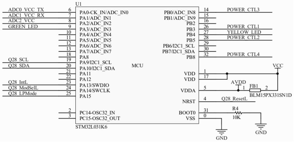
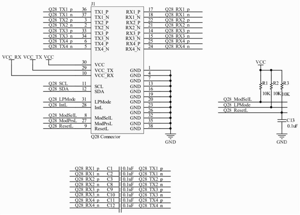
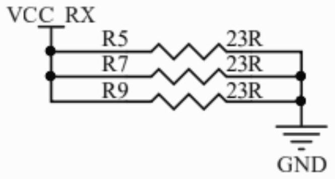
[0061] see Figure 1-Figure 9 , figure 1 It is a schematic diagram of the connection of the controller U1 in the embodiment of the present invention; figure 2 It is a connection schematic diagram of connector J1 in the embodiment of the present invention; image 3 It is a schematic diagram of the connection of the fixed load circuit in the embodiment of the present invention; Figure 4 It is a schematic diagram of the connection of the first load circuit in the embodiment of the present invention; Figure 5 It is a schematic diagram of the connection of the second load circuit in the embodiment of the present invention; Image 6 It is a schematic diagram of the connection of the third load circuit in the embodiment of the present invention; Figure 7 It is a schematic diagram of the connection of the fourth load circuit in the embodiment of the present invention; Figure 8 It is a schematic diagram of the connection of the prompt circuit in the embodiment of the present ...


PUM


Abstract

The invention provides a QSFP (Quad Small Form-factor Pluggable)-based variable-power-consumption high-speed loopback test module, and relates to the technical field of interface testing. The method comprises a master control module and an optical module interface connected with the master control module. The master control module is connected with a load loop group; the optical module interface is also connected with an AC coupling loopback circuit; the power consumption of modules can be set according to requirements, energy is saved, different power consumption requirements can be met through one product, and the modules do not need to be replaced in the testing process. Meanwhile, each functional pin can be tested to detect whether an open circuit and a short circuit exist or not, the result can be read and judged by an upper computer through a register, and a full-coverage test is formed; the magnitude of the input voltage on the optical module interface can be detected through the main control module; moreover, optical fibers which are high in price and short in service life are not needed, and a passive high-speed signal loop is designed in the module, so that the test of high-speed data signal links of a switch and a router can be realized through the passive high-speed signal loop.

Description

technical field [0001] The invention relates to the technical field of interface testing, in particular to a QSFP-based variable power consumption high-speed loopback testing module. Background technique [0002] At present, the types of switches and routers are gradually increasing, and at the same time, there are more and more functions that need to interact with cloud servers. In order to ensure the stability of the final product functions, it is necessary to conduct a comprehensive test on its functional interfaces in advance. [0003] However, the interface testing system currently used for switches and routers has the following problems in use: [0004] 1. At present, the high-speed loopback module is used in the field of port testing of switches and routers, and its rated power consumption is relatively high. When a large number of tests are performed, energy is wasted, which does not meet the current theme of energy conservation and environmental protection; [0005...

Claims


Application Information

Patent Timeline
Patent Type & Authority Applications(China)
IPC IPC(8): H04B10/035H04B10/079H04Q11/00
CPCH04B10/035H04B10/0793H04Q11/0005H04Q11/0062H04Q2011/0083
Inventor 李刚
Owner 迈矽科技(上海)有限公司
Learn More