
Inner and outer edge double-station punching die and punching process thereof

A punching die and double-station technology, which is applied in the field of punching dies with inner and outer edge double-stations and its punching process, can solve the problems of power consumption, inconsistent specifications and sizes, and reduce production efficiency, so as to reduce the use cost and avoid Effect of position shift and improvement of punching efficiency

Pending Publication Date: 2021-12-07
佳昌(天津)精密机械有限公司
View PDF7 Cites 0 Cited by
  • Summary
  • Abstract
  • Description
  • Claims
  • Application Information

AI Technical Summary

Problems solved by technology

[0002] Metal casting parts, such as flywheel housings, brackets, calipers, etc. used in automobiles, during the production process, according to the relevant quality and technical requirements, the parting line burrs and water inlets of rough products with uneven edges must be trimmed , usually, the machining process of rough product parting line burr and water inlet trimming needs milling machine, grinding wheel machine tool, angle grinder, straight grinder and other machine tools, multi-process, multi-station combined linkage to complete, not only Time-consuming, labor-intensive, large investment in manpower and equipment, low production efficiency, high cost, and uneven quality of the products produced. Currently, punching molds have been developed to trim the burrs of the above-mentioned metal casting parts;
[0003] Existing punching dies can only process the parting surface and water inlet of a single outer edge or inner hole of the casting; processing the outer edge and inner hole at the same time in one process requires multiple sets of molds or even multiple equipment to work In order to achieve the effect, it is referred to as single-station outer edge punching or single-station inner hole punching; the casting is placed on the knife set that matches the structure, the upper mold moves down, and the casting is pressed down into the knife set. After passing through the knife group, the punching of the burrs is completed; the burrs of the casting parting line and the water inlet are removed by stamping. The existing punching dies do not have the function of deburring non-standard castings, such as flywheel housings, The specifications and sizes of the bracket and the caliper are inconsistent, the overall thickness of the flywheel housing is greater than that of the bracket and the caliper, and during the casting process of the flywheel housing, bracket, and caliper, there will be irregular through grooves or through holes, and the side walls of the through grooves and through holes There will be burrs. The existing punching dies can only remove the burrs on the edge of the casting, or can only remove the burrs on the side wall of the slot hole of the casting. Half part of the edge burr is removed. For the burr on the lower half of the large thickness and the side wall of the through groove and through hole, the staff needs to use external grinding equipment to remove the part of the burr, which increases the workload for the staff and reduces punching. Mold removal efficiency;
[0004] Existing punching dies cannot perform one-time punching on the water inlet of the casting, and subsequent grinding and cutting are required, which wastes production time and reduces production efficiency, and the thickness of the water inlet is much larger than that of the burrs. Punching and shearing will cause damage to the casting. The existing knife set cannot punch down the water inlet at one time. If the punching is too large, the casting will be scrapped

Method used


Image

  • Inner and outer edge double-station punching die and punching process thereof
  • Inner and outer edge double-station punching die and punching process thereof
  • Inner and outer edge double-station punching die and punching process thereof

Examples


Embodiment 1

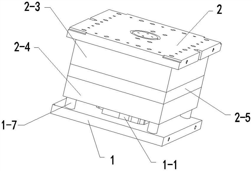
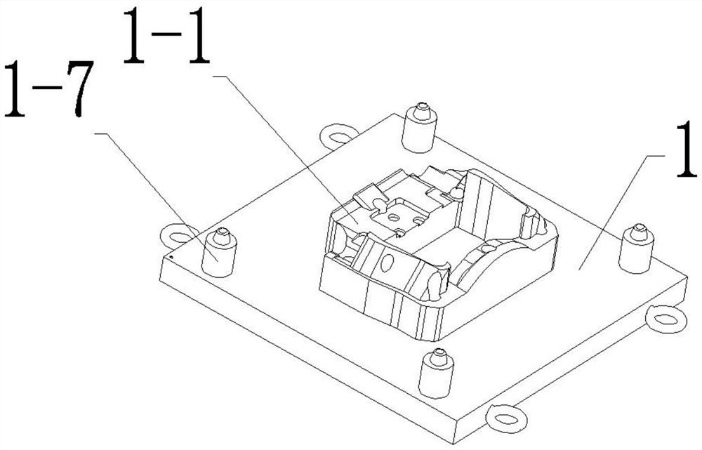
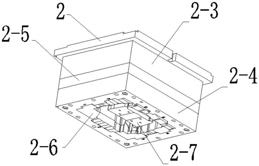
[0061] Please refer to Figure 1-3 , in an embodiment of the present invention, a punching die with inner and outer edges and a punching process thereof, including a bottom plate of the lower die 1, a guide post 1-7, a guide sleeve 2-4, a positioning block 1-1 of the lower die, Upper mold bottom plate 2, connecting plate 2-1, pressure bar 2-21, support plate 2-3, middle plate 2-5, knife block 2-6, punch 2-7, the top of lower mold bottom plate 1 is equipped with Die positioning block 1-1, guide posts 1-7 are respectively installed at the four corners of the bottom plate 1 top of the lower mold, guide sleeves 2-4 are respectively installed at the four corners of the bottom plate 1 of the upper mold, and the guide sleeves 2-4 is used in conjunction with the guide column 1-7; the bottom of the upper mold bottom plate 2 is equipped with a support plate 2-3, and the bottom of the support plate 2-3 is equipped with an intermediate plate 2-5, and the intermediate plate 2 The middle p...

Embodiment 2

[0071] Please refer to Figure 4-5 , in an embodiment of the present invention, a punching die with inner and outer edges and a punching process thereof, further comprising a lower mold double-station positioning block 1-3, and the lower mold double-station positioning block 1-3 is installed on the lower On the top of the mold bottom plate 1, a blanking groove 1-2 is provided inside the bottom mold bottom plate 1, and the blanking groove 1-2 is set on the lower side of the double-station positioning block 1-3 of the bottom mold;

[0072] Specifically, this example replaces the bottom plate 1 of the lower mold and the positioning block 1-1 of the lower mold in Embodiment 1, and is used in combination with Embodiment 1;

[0073] Specifically, the burrs punched by the knife block 2-6 are discharged from the blanking trough 1-2, realizing the collection of burr waste;

[0074] Specifically, this embodiment is used for punching small caliper double-station castings, which can punc...

Embodiment 3

[0083] Please refer to Figure 6 , in an embodiment of the present invention, a punching die with inner and outer edge double stations and its punching process, the lower die backing plate 1-4 is installed on the bottom plate of the lower die, and the backing plate 1-4 of the lower die The top is equipped with positioning blocks 1-5 of the large bracket of the lower die;

[0084] Specifically, this embodiment replaces the bottom plate 1 of the lower mold and the positioning block 1-1 of the lower mold in the first embodiment, and is used in combination with the first embodiment;

[0085] Specifically, this embodiment is for punching of large bracket castings;

[0086] Specifically, the large bracket positioning block of the lower mold in this embodiment is used for the positioning of the large bracket casting;

[0087] A double-station punching die for inner and outer edges and its punching process. The specific punching process of large bracket castings is as follows:

[0...


PUM


Abstract

The invention provides an inner and outer edge double-station punching die and a punching process thereof. The inner and outer edge double-station punching die is characterized in that the punching die comprises a lower die bottom plate, guide columns, guide sleeves, a lower die positioning block, an upper die bottom plate, a connecting plate, a pressing rod, a supporting plate, a middle plate, cutter blocks and a punch, the lower die positioning block is installed at the top of the lower die bottom plate, the guide columns are installed at the four corners of the top of the lower die bottom plate respectively, and the guide sleeves are installed at the four corners of the upper die bottom plate respectively and used in cooperation with the guide columns; and the supporting plate is installed at the bottom of the upper die bottom plate, and the middle plate is installed at the bottom of the supporting plate. According to the inner and outer edge double-station punching die and the punching process thereof, the function of deburring non-standard castings is achieved, inner and outer edges of castings of various sizes and thicknesses can be punched at the same time, the deburring effect is achieved, the punching efficiency is high, a large amount of manpower is reduced, time and labor are saved, and the punching efficiency is greatly improved.

Description

technical field [0001] The invention relates to the technical field of punching dies, in particular to a punching die with inner and outer edges and a punching process thereof. Background technique [0002] Metal casting parts, such as flywheel housings, brackets, calipers, etc. used in automobiles, during the production process, according to the relevant quality and technical requirements, the parting line burrs and water inlets of rough products with uneven edges must be trimmed , usually, the machining process of rough product parting line burr and water inlet trimming needs milling machine, grinding wheel machine tool, angle grinder, straight grinder and other machine tools, multi-process, multi-station combined linkage to complete, not only Time-consuming, labor-intensive, large investment in manpower and equipment, low production efficiency, high cost, and uneven quality of the products produced. Currently, punching molds have been developed to trim the burrs of the ab...

Claims


Application Information

Patent Timeline
Patent Type & Authority Applications(China)
IPC IPC(8): B21D28/14B21D28/02B21D45/04B21D43/00B08B15/04B22D31/00
CPCB21D28/14B21D28/02B21D45/04B21D43/003B08B15/04B22D31/00
Inventor 谈侃
Owner 佳昌(天津)精密机械有限公司
Learn More