Silicon carbide rod clamping device and using method thereof

A technology for clamping devices and silicon carbide rods, applied in the direction of workpiece clamping devices, manufacturing tools, etc., can solve problems that affect the conductivity of silicon carbide rods and clamping devices, cannot be used for silicon carbide rods, and affect the replacement of silicon carbide rods. , achieve the effects of shortening clamping and replacement time, strong clamping reliability, and efficient clamping and replacement

Active Publication Date: 2021-12-07
SGIS SONGSHAN CO LTD
View PDF6 Cites 1 Cited by
  • Summary
  • Abstract
  • Description
  • Claims
  • Application Information

AI Technical Summary

Problems solved by technology

In this connection method, after many tests, a large amount of coal will condense on the surface of the nut, which will affect the replacement of the silicon carbide rod, and the coal bonding on the surface of the bolt and the nut will cause corrosion of the bolt and nut, which will affect the connection between the silicon carbide rod and the nut. Conductivity of the holding device
[0004] Moreover, at present, for the colloidal layer index measuring instrument, under normal circumstances, it is necessary for the staff to use tools such as wrenches to replace the silicon carbide rods within the replacement cycle of the silicon carbide rods, and the replacement efficiency is low; and tools such as wrenches are used. Dismantling and tightening the silicon carbide rods poses a safety risk during use
[0005] In addition, the existing clamping device can only clamp silicon carbide rods of one size, and cannot be used for silicon carbide rods of different sizes

Method used


Image

  • Silicon carbide rod clamping device and using method thereof
  • Silicon carbide rod clamping device and using method thereof

Examples


Embodiment approach

[0080] According to a preferred embodiment of the present invention, the silicon carbide rod clamping device further includes:

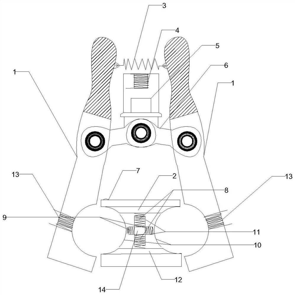
[0081] Return spring 3, the two ends of which are respectively connected to the inside of the upper end of the left clamping arm and the right clamping arm, and make the left clamping arm and the right clamping arm form a certain angle;

[0082] Push-pull mechanism 6, the two ends of which are respectively hinged with the middle parts of the left clamping arm and the right clamping arm;

[0083] A magnetic suction mechanism, which is located between the left clamping arm and the right clamping arm, and above the push-pull mechanism 6, is connected to the middle of the push-pull mechanism 6, and can make the magnetic suction mechanism energized The magnetic force generated last can pull the push-pull mechanism 6 upwards, so that the left clamping arm and the right clamping arm rotate inward respectively to clamp the silicon carbide rod.

[0084] In t...

Embodiment 1

[0125] The silicon carbide rod clamping device of the present embodiment is as figure 1 As shown, the operation is as follows:

[0126] The first step: place the upper clamping seat 2, the lower clamping seat 12, the movable clamping part 10, the support seat 14, and the structure composed of the vertical spring 8 and the horizontal spring 9 on the two silicon carbide rods to be clamped Between; wherein, the vertical spring 8 and the horizontal spring 9 are respectively placed in the limit card slot 11 provided on the support base 14 to ensure the linear movement of the spring.

[0127] Second step: when the first electromagnetic coil 4 is not energized, the clamping arm 1 (that is, the left clamping arm and the right clamping arm) is under the support of the return spring 3, and the left clamping arm and the right clamping arm will A certain initial angle is formed, so that the two clamping grooves arranged on the inner side of the lower end of the clamping arm 1 are in a l...


PUM


Abstract

The invention belongs to the technical field of clamping devices, and particularly relates to a silicon carbide rod clamping device and a using method thereof. The silicon carbide rod clamping device comprises clamping arms, second electromagnetic coils, a second power supply, a supporting seat, an elastic part, clamping seats, and movable clamping parts, wherein the clamping arms comprise a left clamping arm and a right clamping arm which are symmetrically arranged; clamping grooves are formed in the inner side faces of the lower ends of the left clamping arm and the right clamping arm correspondingly; the second electromagnetic coils are mounted on the clamping grooves; the second power supply is electrically connected with the second electromagnetic coils; the supporting seat is located in the middle of the two clamping grooves; the elastic part is connected onto the supporting seat and can independently apply elastic force in the upper direction, the lower direction, the left direction and the right direction of the supporting seat; the two clamping seats are located above and below the elastic part respectively and connected with the elastic part, and pre-clamping parts are arranged on the left bottom face and the right bottom face of each clamping seat respectively; and the two movable clamping parts are symmetrically connected to the left side and the right side of the elastic part. The silicon carbide rod clamping device provided by the invention is small in size, compact in structure, rapid in clamping, high in replacement efficiency and capable of adapting to silicon carbide rods with different sizes.

Description

technical field [0001] The invention belongs to the technical field of clamping devices, and in particular relates to a silicon carbide rod clamping device and a use method thereof. Background technique [0002] In view of the production nature of iron and steel enterprises or non-ferrous enterprises, it is necessary to analyze the chemical properties of the incoming raw material coal, such as the gelatinous layer index. At present, for the gelatinous layer index, the enterprise chooses the gelatinous layer index tester, which is composed of furnace bricks, silicon carbide rods, probes, asbestos gaskets, and power supplies. [0003] However, the connection between the silicon carbide rods and the power supply currently used by enterprises is hard-connected by bolts, such as figure 2 shown. In this connection method, after many tests, a large amount of coal will condense on the surface of the nut, which will affect the replacement of the silicon carbide rod, and the coal bo...

Claims


Application Information

Patent Timeline
Patent Type & Authority Applications(China)
IPC IPC(8): B25B11/00
CPCB25B11/002
Inventor 张煜平曹文发吴东武梁金海廖卉黎佐洋徐楚力
Owner SGIS SONGSHAN CO LTD
Why Eureka
Try Eureka