Disc brake device for kinetic energy conversion of new energy automobile

A new energy vehicle, kinetic energy conversion technology, applied in the direction of control devices, auxiliary drive devices, brakes, etc., can solve the problems of affecting the service life of linear motors, the wear of convex teeth and cogging, and the aggravation of component loss, so as to facilitate processing and improve Braking ability, simple structure effect

Active Publication Date: 2021-12-07
杭州智科精密机械有限公司
View PDF11 Cites 0 Cited by
  • Summary
  • Abstract
  • Description
  • Claims
  • Application Information

AI Technical Summary

Problems solved by technology

[0005] However, in the actual use of the kinetic energy recovery device of this application, we found that when the state switching at both ends of the torsion elastic member relies on the telescopic movement of the linear motor, and uses the engagement of the convex teeth and the tooth grooves to achieve rotational docking, although It can realize docking and switching, but the wear and tear on the convex teeth and the tooth grooves is extremely serious during the whole process, and because the real-time positions and states of the corresponding convex teeth and tooth grooves are not fixed, it is easy to cause rigidity when the convex teeth and tooth grooves are docked. Contact collision, that is, the convex teeth are not aligned with the tooth grooves, which not only further aggravates the loss of the component, but also makes the linear motor continue to work and elongate. It cannot be stretched, and at the same time seriously affects the service life of its linear motor. Therefore, we propose a disc brake device for kinetic energy conversion of new energy vehicles

Method used


Image

  • Disc brake device for kinetic energy conversion of new energy automobile
  • Disc brake device for kinetic energy conversion of new energy automobile
  • Disc brake device for kinetic energy conversion of new energy automobile

Examples


Embodiment Construction

[0037] Next, the technical solutions in the embodiments of the present invention will be described in connection with the drawings of the embodiments of the present invention, and it is understood that the described embodiments are merely the embodiments of the present invention, not all of the embodiments. Based on the embodiments of the present invention, all other embodiments obtained by those of ordinary skill in the art are in the range of the present invention without making creative labor premise.

[0038] The present invention provides a technical solution:

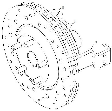
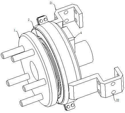
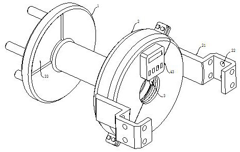
[0039] See Figure 1-2 As shown, a disc brake device for new energy vehicle kinetic energy conversion, includes a roulette 1 in a car hub drive shaft end and is used in the brake disc mounting, the wheel disk 1 and the brake disc;

[0040] It also includes a mounting jacket 2, and both sides of the mounting collar 2 are provided with a mounting bracket 21, and the two mounting brackets 21 are provided with a mounting h...


PUM


Abstract

The invention discloses a disc brake device for kinetic energy conversion of a new energy automobile. The device comprises a wheel disc which is positioned at the end part of an automobile hub driving shaft and is used for mounting a brake disc, the wheel disc is coaxial with the brake disc, the disc brake device comprises a mounting lantern ring, mounting brackets are arranged on the two sides of the mounting lantern ring, a through mounting hole is formed in each of the two mounting brackets, and the two mounting brackets are mounted on an automobile suspension through bolts, wrap the outer side of the driving shaft and rotate coaxially with the wheel disc. The kinetic energy conversion braking device of the new energy automobile is different from the prior art, and in the braking process of the new energy automobile, through synchronous touch of the electromagnetic butt joint components, when the automobile is braked, an elastic energy storage mechanism is driven to convert the kinetic energy of the automobile into elastic potential energy; and in the energy storage process, the continuously increased elastic potential energy can provide reverse elastic resistance for the wheel disc of the automobile so as to assist service braking, so that the braking effect of the new energy automobile is improved.

Description

Technical field [0001] The present invention relates to new energy vehicles converts kinetic braking technology field, in particular to a disc brake device for converting the kinetic energy of the new energy vehicles. Background technique [0002] Most new energy vehicles prior to use conventional automotive braking systems, the brake wheel and brake drum or brake disc to the vehicle kinetic energy dissipation as heat into the air; or adopt a negative torque generated by the motor forms a part of system moving energy recovery to the power cell. [0003] However, the traditional vehicle kinetic energy dissipated as heat into the air the way, will make the brakes fast heating, heat fading phenomenon occurs, resulting in an increase braking distance, even result in brake failure, but also greatly shorten the brake shoe service life, a large amount of dust contamination and affect the braking ability; in addition, although some new energy vehicles additionally equipped with a brake e...

Claims


Application Information

Patent Timeline
Patent Type & Authority Applications(China)
IPC IPC(8): B60T1/10B60K25/00
CPCB60T1/10B60K25/00
Inventor 洪伟纯
Owner 杭州智科精密机械有限公司
Why Eureka
Try Eureka