Waste discharging device for protective film waste and waste discharging method

A technology of waste discharge device and protective film, which is used in thin material handling, transportation and packaging, and winding strips, etc., can solve the problems of product inclination, product bending, and low efficiency, so as to reduce labor costs and waste discharge. time, and the effect of improving waste discharge efficiency

Inactive Publication Date: 2021-12-07
成都冠佳科技有限公司
View PDF0 Cites 0 Cited by
  • Summary
  • Abstract
  • Description
  • Claims
  • Application Information

AI Technical Summary

Problems solved by technology

[0002] At present, the waste discharge of the transparent protective film on the top layer of the existing product is done manually, which is easy to bend the product during the waste discharge process, and the efficiency is low; in addition, manual waste discharge is easy to cause the product to tilt during the waste discharge process, resulting in Product scrap

Method used


Image

  • Waste discharging device for protective film waste and waste discharging method
  • Waste discharging device for protective film waste and waste discharging method
  • Waste discharging device for protective film waste and waste discharging method

Examples


Embodiment 1

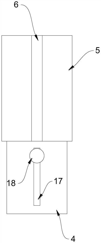
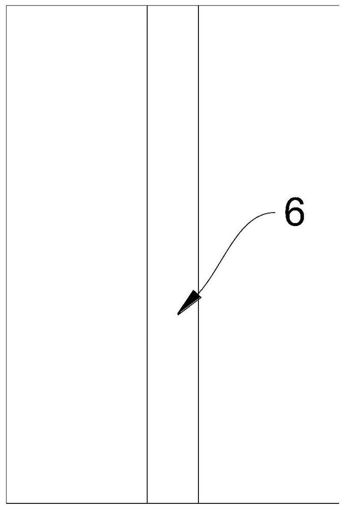
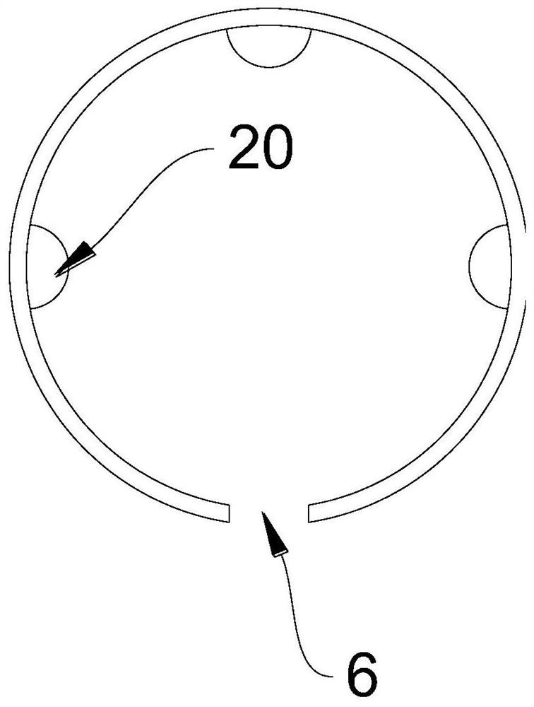
[0054] Please refer to Figure 1-11 , this embodiment provides a protective film waste discharge device, including: a frame 1, a tape main body 2, a conveying roller set 3, a driving roller 4, a winding roller 5, a first opening 6, an accommodating chamber 7, a second opening 8. The first clamping plate 9, the second clamping plate 10, the driving member 11, the installation groove 12, the first driving groove 13, the second driving groove 14, the first sliding rod 15, the second sliding rod 16, the limit Groove 17, driving handle 18, stop groove 19 and limiting rib 20.

[0055] The frame 1 has a conveying roller group 3 for conveying the tape main body 2; the driving roller 4 is rotatably arranged on the frame 1; the winding roller 5 is detachably connected with the driving roller 4, and can rotate synchronously with the driving roller 4 to The protective film is wound on the take-up roller 5; the clamping assembly is used to clamp the end of the protective film.

[0056] I...

Embodiment 2

[0098] Please combine Figure 12 , this embodiment is basically the same as Embodiment 1, except that two groups of waste discharge devices are symmetrically arranged on the frame 1, and the central axis of the driving roller 4 in the two groups of waste discharge devices is perpendicular to the central axis of the conveying roller group 3; wherein The driving mode of the driving roller 4 in the two sets of waste discharge devices can be driven by the motor alone, or the existing transmission mechanism can be used to connect with the conveying roller group 3 .

[0099] It should be noted that the rotational speeds of the two driving rollers 4 should be the same to avoid the belt main body 2 from inclining.

[0100] The purpose of the design of the two sets of waste discharge devices is to separately collect the half-divided protective film (due to technical reasons, part of the protective film is divided into two halves along the axial direction of the tape main body 2) to imp...


PUM


Abstract

The invention discloses a waste discharging device for protective film waste, and relates to the field of waste discharging devices. The waste discharging device comprises a rack, a driving roller, a winding roller and a clamping assembly; the rack is provided with a conveying roller set used for conveying a rubber belt body; the driving roller is rotationally arranged on the rack; the winding roller is detachably connected with the driving roller and can synchronously rotate along with the driving roller, so that a protective film is wound on the winding roller; the clamping assembly is used for clamping the end of the protective film. The waste discharging device can automatically collect the protective film waste, and the labor cost and the rejection rate of products are greatly reduced while the waste discharging efficiency is guaranteed. The waste discharging method is achieved on the basis of the waste discharging device, rapid waste discharging can be achieved through the waste discharging device, the waste discharging method is easy and convenient to operate, and the waste discharging efficiency of the protective film waste can be greatly improved.

Description

technical field [0001] The invention relates to the field of waste discharge devices, in particular to a protective film waste discharge device and a waste discharge method. Background technique [0002] At present, the waste discharge of the transparent protective film on the top layer of the existing product is done manually, which is easy to bend the product during the waste discharge process, and the efficiency is low; in addition, manual waste discharge is easy to cause the product to tilt during the waste discharge process, resulting in Product scrapped. [0003] In view of this, this application is proposed. Contents of the invention [0004] The first object of the present invention is to provide a protective film waste discharge device, which can automatically collect the protective film waste, greatly reduces labor costs and product scrap rate while ensuring waste discharge efficiency. [0005] The second object of the present invention is to provide a protecti...

Claims


Application Information

Patent Timeline
Patent Type & Authority Applications(China)
IPC IPC(8): B65H18/10B65H20/02B65H75/28B65H41/00B65H75/18
CPCB65H18/10B65H20/02B65H75/285B65H41/00B65H75/18B65H2701/19B65H2701/377B65H2301/412
Inventor 左宇娟彭开云
Owner 成都冠佳科技有限公司
Why Eureka
Try Eureka