
Carbon fiber wound gas cylinder and monitoring method of health state of gas cylinder

A technology for winding gas cylinders and health status, which is applied in the field of monitoring carbon fiber winding gas cylinders and their health status. , small size, the effect of reducing the impact

Active Publication Date: 2021-12-07
苏州辰航致远智能科技有限公司
View PDF11 Cites 0 Cited by
  • Summary
  • Abstract
  • Description
  • Claims
  • Application Information

AI Technical Summary

Problems solved by technology

The hydrostatic test needs to install the gas cylinder on a special hydrostatic test facility. The annual inspection interval is too long, and the operation is inconvenient. Real-time monitoring cannot be achieved, and the health of the gas cylinder cannot be judged based on the measured volume change of the gas cylinder. state

Method used


Image

  • Carbon fiber wound gas cylinder and monitoring method of health state of gas cylinder
  • Carbon fiber wound gas cylinder and monitoring method of health state of gas cylinder
  • Carbon fiber wound gas cylinder and monitoring method of health state of gas cylinder

Examples


Embodiment 1

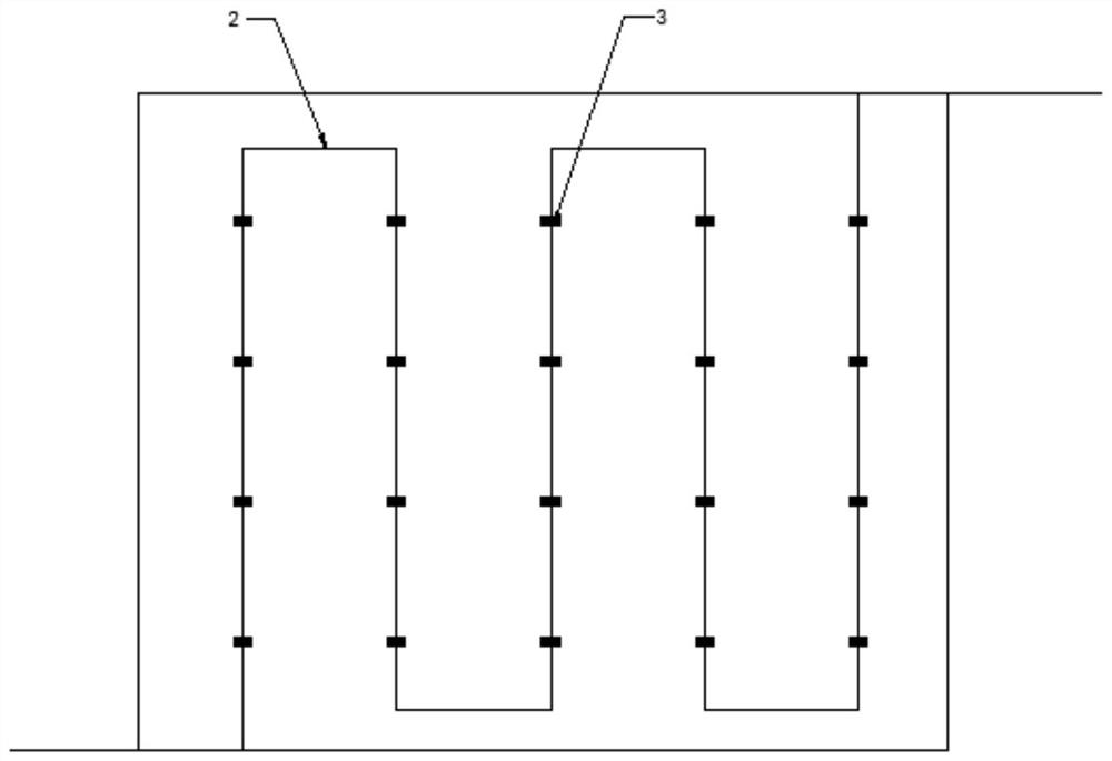
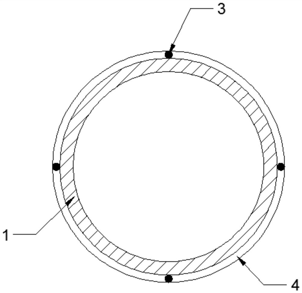
[0054] like Figure 1 - Figure 3 , The carbon fiber of the present invention provide a wound cylinder, comprising a cylinder body, the cylinder body 1 with an optical fiber 2 is wound uniformly with a number of four grid points 3, wherein the optical fiber 2 using four spirally wound fabric sticker or serpentine wound cloth paste, a number of grid points 3 are each arranged on the optical fiber 2, the optical fiber 2 is wound on either the cylinder body 1 to ensure a radial section on the gate location point 3 are laid with a four-point gate 3 , point 3 along the axial direction of the gate body cylinder 1 arranged in a straight line and the adjacent two gate four points the same axial distance between the 3 (grid points of optical fibers 2 bonded by the glue 3 of the cylinder liner, gas bottle occurs upon expansion, it will lead to the gate region stretching, whereby demodulated center wavelength of reflected light is changed, whereby there results a strain of the gate region). L-...

Embodiment 2

[0083] This embodiment differs from Embodiment 1 This embodiment is characterized in that the formula (4), a value of is 0.7, b is a value of 0.3. Values ​​as follows:

[0084] Hoop stress and axial stress graph is obtained when the test cylinder by normal operation, such as Figure 4 , According to the hoop stress and axial stress can be seen the graph, the peripheral cylindrical portion of the cylinder to stress axial stress ratio of about 7: 3, and thus taking a is 0.7, b is 0.3, the overall volume to obtain the coefficient of variation :

[0085] K 1 = 0.7x 1 + 0.3y 1 ,

[0086] α, β, γ, δ value of four coefficients:

[0087] α = 0.7m,

[0088] β = 0.3m,

[0089] γ = 0.7 (1-m),

[0090] δ = 0.3 (1-m);

[0091] K possible values ​​between (0,1), according to a fatigue test cylinders, to obtain a graph showing the relationship between the K value and the number of fatigue tests, such as Figure 5 Shown to 10000,7500,3000 dividing point can be obtained as evaluation rules:

[0092]...

Embodiment 3

[0094] Example Example of the present embodiment that the difference between the two, four spiral-wound optical fiber cloth paste, such as Image 6 , The optical fiber and the cylinder body 2 to the circumferential angle of [theta] 1, the cylinder circumferential elongation of the gate region (grid point) is Δεcosθ, axial elongation of the cylinder of the gate region is Δεsinθ.


PUM


Abstract

The invention provides a carbon fiber wound gas cylinder. The gas cylinder comprises a gas cylinder body, n optical fibers with a plurality of grid points are uniformly wound on the gas cylinder body, and the plurality of grid points are uniformly distributed on each optical fiber; and when the optical fibers are wound, it is ensured that the n grid points are uniformly distributed on the radial section of the position of any grid point on the gas cylinder body, the grid points are arranged into n straight lines in the axial direction of the gas cylinder body, and the axial distances between every two adjacent grid points are the same. A gas cylinder health state evaluation equation is established, and the local deformation condition of the gas cylinder is measured by combining wavelength data returned by the demodulation optical fiber to obtain the fatigue state of a certain position of the gas cylinder and the overall health state.

Description

Technical field [0001] The present invention belongs to the technical field of carbon fibers is wound cylinder, particularly relates to a method for monitoring the carbon fiber winding cylinder and its state of health. Background technique [0002] Carbon fiber winding cylinder volume change is a very important indicator of the health status of the cylinder, the cylinder is excessively large change in volume is an important manifestation of fatigue of the cylinder. For the change in volume of carbon fibers wound cylinders commonly used method for detecting water pressure test, pressure test is one of the elements of the inspection cylinders for cylinders containing hydrogen, the need to check every three years. Health cylinder hydrostatic test needs to be installed on a dedicated hydrostatic testing facilities, inspection interval is too long and inconvenient operation can not achieve real-time monitoring of gas cylinders can not be determined according to the measured change in ...

Claims


Application Information

Patent Timeline
IPC IPC(8): F17C1/00F17C13/00G01B11/16
CPCF17C1/00F17C13/002G01B11/18F17C2201/0104F17C2201/035Y02E60/32
Inventor 徐东
Owner 苏州辰航致远智能科技有限公司
Learn More