Optical fiber tension measuring device and system

A technology of tension measurement and optical fiber, which is applied in the field of tension detection, can solve the problems of inaccurate tension detection and errors, and achieve the effect of accurate tension and detection

Inactive Publication Date: 2021-12-07
西安柯莱特信息科技有限公司
View PDF0 Cites 0 Cited by
  • Summary
  • Abstract
  • Description
  • Claims
  • Application Information

AI Technical Summary

Problems solved by technology

[0005] The purpose of the present invention is to provide a kind of optical fiber tension measuring device and system for the above-mentioned deficiencies in the prior art, so that when the tension detection device of the mechanical structure in the prior art detects the tension, the tension detection device itself will also Deformation occurs under the action of tension. Generally, when calcul

Method used


Image

  • Optical fiber tension measuring device and system
  • Optical fiber tension measuring device and system
  • Optical fiber tension measuring device and system

Examples


Embodiment Construction

[0021] To make the purpose, technical solutions and advantages of the embodiments of the present invention more clear, the embodiments of the present invention will be further described in detail below in conjunction with the accompanying drawings. Here, the exemplary embodiments and descriptions of the present invention are used to explain the present invention, but not to limit the present invention.

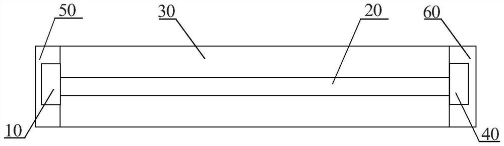
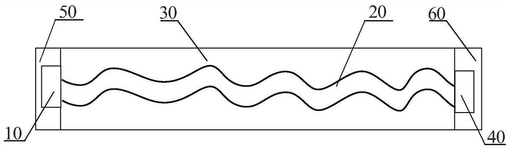
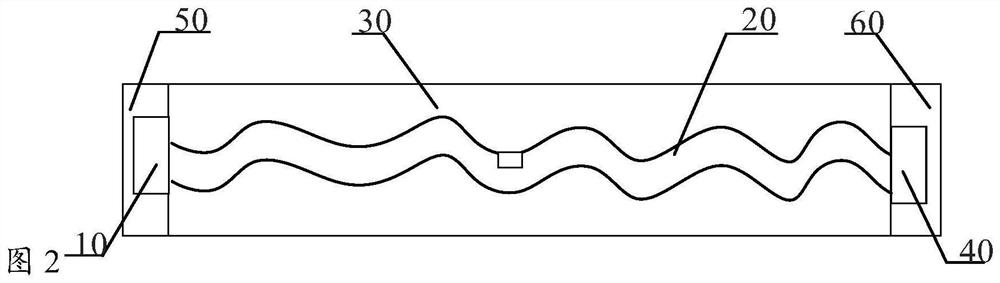
[0022] figure 1 A schematic structural view of an optical fiber tension measuring device provided in an embodiment of the present invention; figure 1 As shown, the present application provides an optical fiber tension measuring device, which includes: a light source 10, a first force receiving part 50, a second force receiving part 60, an elastic part 30, an optical fiber 20 and a light detector 40, and the elastic part 30 is wrapped and arranged on Outside the optical fiber 20, the light source 10 and the photodetector 40 are respectively arranged at the two ends of the elas...


PUM


Abstract

The invention relates to an optical fiber tension measuring device and system, and in particular relates to the field of tension detection. The optical fiber tension measuring device comprises a light source, a first stress part, a second stress part, an elastic part, an optical fiber and an optical detector, when tension needs to be detected, the tension acts on the first stress part and the second stress part of the optical fiber tension measuring device, under the action of the first stress part and the second stress part, the elastic part deforms, the elastic part acts tension and pressure on the optical fiber to enable the optical fiber to deform, and then the transmission loss of the optical fiber is changed, so that the light intensity of an optical signal emitted through the optical fiber is changed, and the emergent light intensity of the optical signal is detected through the optical detector; and according to the corresponding relationship between the light intensity and the to-be-measured tension, the to-be-measured tension is acquired.

Description

technical field [0001] The present application relates to the field of tension detection, in particular, to an optical fiber tension measurement device and system. Background technique [0002] The tensile force is within the elastic limit, and the deformation of the object under the action of the external force is proportional to the external force. The deformation varies with the direction of the force, and the force that makes the object extend is called "pull force" or "tension force". [0003] In the prior art, the tension is measured mainly by a tension device, and the calculation principle of the tension device is calculated by the formula f=w / s, where f represents the tension, w represents the length, and s represents the elastic coefficient of the spring, [0004] However, when the tension detection device of the mechanical structure in the prior art detects the tension, the tension detection device itself will also be deformed under the action of the tension. Gene...

Claims


Application Information

Patent Timeline
IPC IPC(8): G01L1/24
CPCG01L1/242
Inventor 吉鹏勃范鸿
Owner 西安柯莱特信息科技有限公司
Why Eureka
Try Eureka