Collecting structure of battery and battery

A battery and current collector technology, applied in the direction of electrode carrier/current collector, etc., can solve the problems of low current conduction capacity, increased battery internal resistance, large internal resistance, etc., and achieve improved rate performance, high energy density, and heat generation rate. small effect

Pending Publication Date: 2021-12-07
刘振
View PDF4 Cites 2 Cited by
  • Summary
  • Abstract
  • Description
  • Claims
  • Application Information

AI Technical Summary

Problems solved by technology

[0003] The traditional current collection method includes the use of single or multiple tabs connected to the pole as the current collection method, which has low current conduction capacity, high internal resistance, uneven current distribution during charging and discharging, and it is difficult to achieve high current. Discharge
As a further improvement, current collectors are introduced into the end faces of the electrodes, and the current collectors are connected to the poles through welded or integrally connected bendable meta

Method used


Image

  • Collecting structure of battery and battery
  • Collecting structure of battery and battery
  • Collecting structure of battery and battery

Examples


Embodiment 1

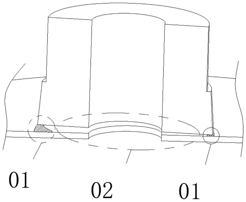
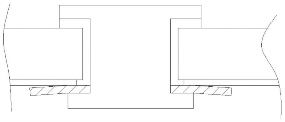
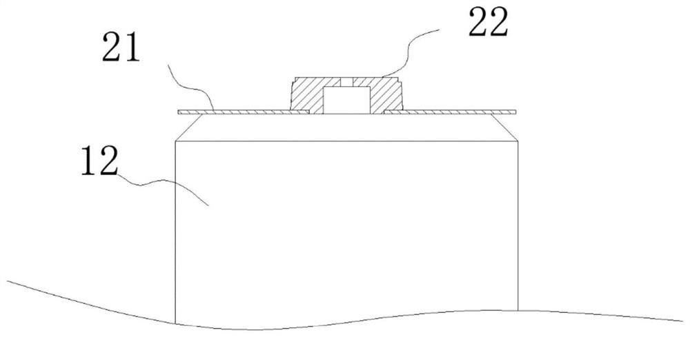
[0044] refer to Figure 3-Figure 4 The embodiment of the present invention provides a current collecting structure of a battery. The battery includes a battery cell 12. The current collecting structure includes a current collecting plate 21 and a current collecting post 22. One end face of the current collecting plate 21 is welded to an electrode end face of the battery cell 12. , the other end face of the collecting plate 21 is welded with the collecting column 22;

[0045] The current collecting post 22 includes a soldering pad 221 and an annular boss 222 formed on the soldering pad 221. A through hole 211 matching the annular boss 222 is opened on the collector disc 21, and the protrusion height of the annular boss 222 is the same as that of the through hole. The holes 211 have the same depth, and the annular boss 222 is welded and fixed to the collector plate 21 at the through hole 211 .

[0046] Annular welding is performed between the through hole 211 of the collector p...

Embodiment 2

[0058] refer to Figure 5-Figure 10 ,and Figure 12-Figure 17 , the embodiment of the present invention provides a battery, including a casing 11 and a battery cell 12 arranged in the casing 11, and the two ends of the battery cell 12 are respectively provided with a positive electrode current collecting structure 30 and a negative electrode current collecting structure 40, and the positive electrode current collecting structure 30 adopts the battery current collecting structure provided in Example 1.

[0059] The positive electrode potential of the battery is high, so that the current passing through the positive electrode is large, which has a great test on the internal resistance of the current collecting structure at the positive electrode and the current conduction efficiency, especially in the process of charging and discharging with a large current. The current structure is prone to heat generation, and the current conduction efficiency cannot meet the requirements of ...


PUM


Abstract

The invention provides a current collecting structure of a battery, the battery comprises a battery cell, the current collecting structure comprises a current collecting disc and a current collecting column, one end face of the current collecting disc is welded with one electrode end face of the battery cell, and the other end face of the current collecting disc is welded with the current collecting column; and the current collecting column comprises a welding disc and an annular boss formed on the welding disc, a through hole matched with the annular boss is formed in the current collecting disc, the protruding height of the annular boss is the same as the depth of the through hole, and the annular boss is welded and fixed to the current collecting disc at the position of the through hole. According to the current collecting structure, the contact area between the current collecting disc and the current collecting column is increased, and the girth welding is carried out in a seam welding manner, so that large current can pass through the current collecting structure, the rate capability of the battery is improved, the space is saved, more electric quantity can be stored in the same space, and the energy density is relatively high. When a large current passes through the current collecting structure provided by the invention, the conduction rate of the current is high, the resistance is low, and the heating rate is small.

Description

technical field [0001] The invention relates to the technical field of lithium battery design and production, in particular to a battery current collecting structure and the battery. Background technique [0002] Lithium batteries stand out among many types of batteries due to their advantages of high energy density, high voltage, high rate performance and long life. According to the packaging type, lithium batteries are generally divided into cylindrical lithium batteries, square lithium batteries and soft-pack lithium batteries. , Cylindrical lithium batteries have been widely used due to their high product yield and high capacity. The improvement of high-current charge-discharge performance has always been a hot topic in the research of cylindrical lithium batteries, and the design of the current collection method has a non-negligible impact on the realization of high-current charge-discharge performance. [0003] The traditional current collection method includes the us...

Claims


Application Information

Patent Timeline
IPC IPC(8): H01M4/78H01M4/64
CPCH01M4/78H01M4/64Y02E60/10
Inventor 刘振
Owner 刘振
Why Eureka
Try Eureka