Heart valve prosthesis and heart valve prosthesis system

A technology for artificial heart valves and protruding parts, which is applied in the field of artificial heart valves and artificial heart valve systems, and can solve problems such as paravalvular leakage

Pending Publication Date: 2021-12-10
LIFETECH SCIENTIFIC (SHENZHEN) CO LTD
View PDF14 Cites 2 Cited by
  • Summary
  • Abstract
  • Description
  • Claims
  • Application Information

AI Technical Summary

Problems solved by technology

[0006] Based on this, it is necessary to provide an artificial heart valve to at least solve the problem of paravalvular leakage after the artificial heart valve is implanted in the prior art

Method used


Image

  • Heart valve prosthesis and heart valve prosthesis system
  • Heart valve prosthesis and heart valve prosthesis system
  • Heart valve prosthesis and heart valve prosthesis system

Examples


no. 1 example

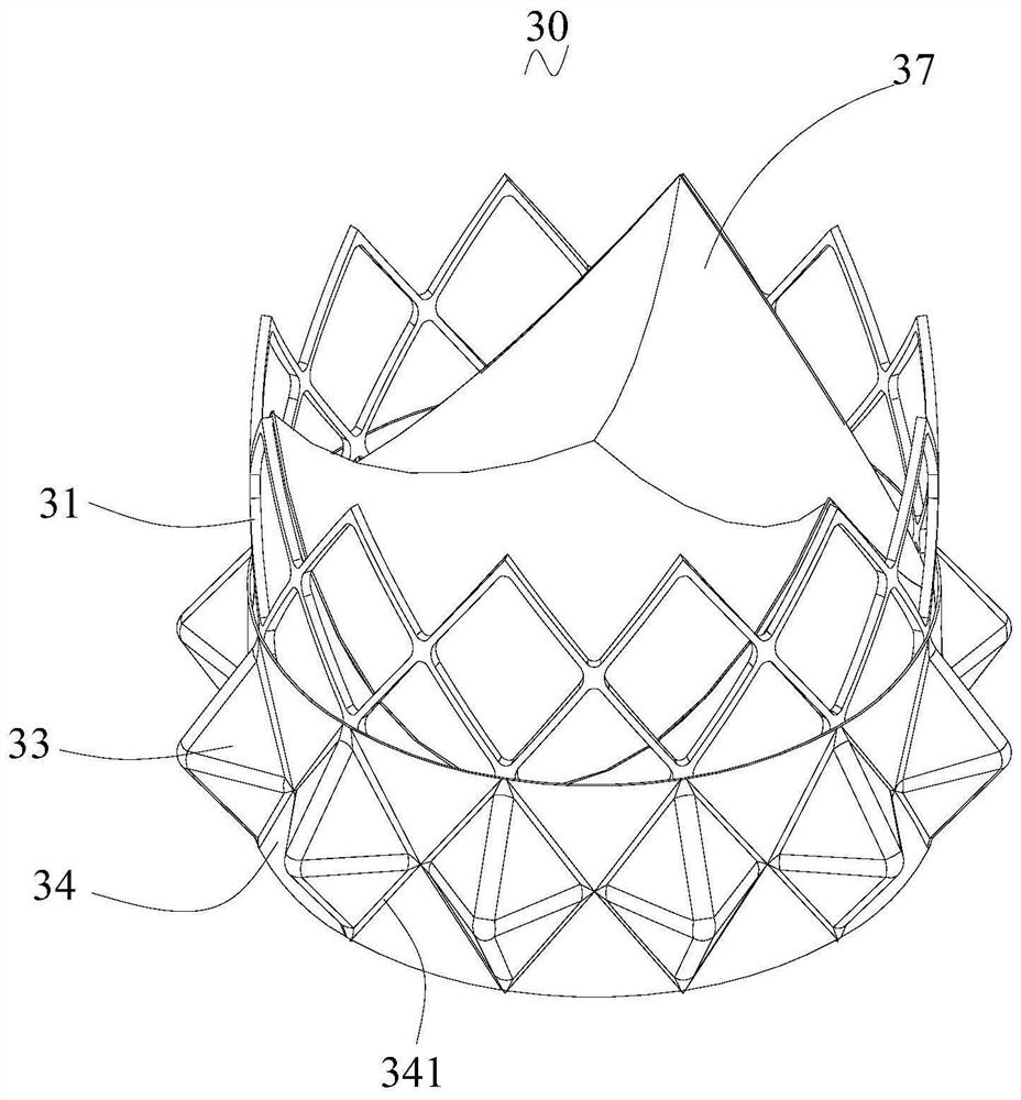
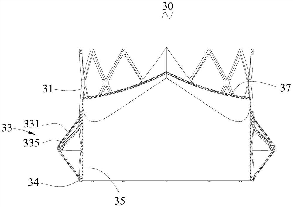
[0035] see figure 2 with image 3 , an embodiment of the present invention provides an artificial heart valve 30 , including a valve frame 31 , at least one protruding structure 33 , an inner skirt 35 and leaflets 37 .

[0036] The inner skirt 35 is fixed on the frame of the unit cell 312 by sewing, and the inner skirt 35 is positioned at the inner side of the petal frame 31. The inner skirt 35 can be made of PET (Polyethylene Terephthalate, polyester resin), PTFE (Poly TetraFluoroethylene, It should be noted that the "blocking" in this embodiment refers to preventing the blood from penetrating from one side to the other.

[0037] The contour of the distal end of the inner skirt 35 is trimmed according to the contour of the distal end of the valve frame 31, and the contour of the proximal end of the inner skirt 35 can be trimmed according to the contour of the proximal end of the valve frame 31 or directly adopts a flat mouth.

[0038] see Figure 4 with Figure 5 The pet...

no. 2 example

[0053] The number of protruding structures 43 in the second embodiment is multiple, wherein at least one protruding structure 43 includes a plurality of elastic pieces 435, and a part of the elastic pieces 435 of the multiple elastic pieces 435 of the protruding structure 43 are connected to the The proximal end is connected, and another part of the elastic member 435 is connected with the distal end of the cell. In the compressed state, there is an axial distance between the elastic member 435 connected to the proximal end of the unit cell and the elastic member 435 connected to the distal end of the unit cell, so that the protruding structure 43 is radially compressed to produce a circumferentially extending folds.

[0054] The number of elastic members 435 of each protruding structure 43 is two for illustration. Specifically, see Figure 9 with Figure 10 , in this embodiment, the number of elastic members 435 of each protruding structure 43 is two. Certainly, in other ...

no. 3 example

[0058]The difference between the third embodiment and the second embodiment is that, in the compressed state, there is a circumferential distance between the elastic member 535 connected to the proximal end of the unit cell 312 and the elastic member 535 connected to the distal end of the unit cell 312 , and there is no axial gap between the two elastic members 535 , and in the compressed state, the protruding structure 53 can produce folds 532 that bend and extend. It should be noted that the fact that the two elastic pieces 535 have no axial gap means that the free end of one elastic piece 535 is located within the axial length interval of the other elastic piece 535 .

[0059] see Figure 11 , in this embodiment, the sum of the lengths of the two elastic members 535 is greater than the axial length of the mesh 313, so that the two elastic members 535 do not have an axial gap, and the ends of the two elastic members 535 are set aside from each other. The protruding structur...


PUM


Abstract

The invention relates to a heart valve prosthesis and a heart valve prosthesis system. The heart valve prosthesis comprises a valve frame and at least one protruding structure, the protruding structure comprises a protruding part, the protruding part is arranged on the valve frame and protrudes towards the outer side of the valve frame, and the protruding part is constructed to be capable of forming wrinkles when being compressed in the radial direction. After the artificial heart valve is implanted into the human body, the protruding parts in the protruding structures make corresponding contact with the autologous valve ring, the protruding parts can be subjected to the radial compression effect of the autologous valve ring, wrinkles formed by the protruding parts make contact with the autologous valve ring, the number of contact points of the protruding parts and the inner wall of the autologous valve ring can be increased, the adherence can be improved, and the size of the gap formed between the protruding part and the autologous valve ring is reduced, the flow speed of blood flowing through the gap can be reduced, protein in the blood is deposited in the gap, thrombus is formed, the gap can be blocked, and then perivalvular leakage is prevented.

Description

technical field [0001] The invention relates to the field of interventional medical devices, in particular to an artificial heart valve and an artificial heart valve system. Background technique [0002] At present, heart valve disease has become one of the common cardiovascular diseases. Although thousands of patients around the world can benefit from surgical valve replacement every year, there are still a large number of patients due to advanced valve disease, advanced age and multiple diseases. Unable to undergo surgical treatment due to complications and other reasons. [0003] Interventional artificial valve surgery can overcome the above-mentioned shortcomings. In 2002, Cribier et al. implanted a stent with an artificial valve into the position of the diseased aortic valve in the human body. After the operation, the hemodynamics of the patients were significantly improved, and the quality of life was improved. In recent years, with the continuous improvement of inte...

Claims


Application Information

Patent Timeline
Patent Type & Authority Applications(China)
IPC IPC(8): A61F2/24
CPCA61F2/2418
Inventor 赖柳山
Owner LIFETECH SCIENTIFIC (SHENZHEN) CO LTD
Why Eureka
Try Eureka