
Temporary bracket arranged by utilizing steel casings and construction method thereof

A steel casing and bracket technology, which is applied in the direction of foundation structure engineering, construction, sheet pile walls, etc., can solve the problems of pile body structure stress and appearance quality are greatly affected, installation and removal are difficult, and construction technology is complicated. Achieve the effect of shortening the construction period, simple construction method and good safety performance

Pending Publication Date: 2021-12-10
ANHUI ROAD & BRIDGE GRP +1
View PDF0 Cites 0 Cited by
  • Summary
  • Abstract
  • Description
  • Claims
  • Application Information

AI Technical Summary

Problems solved by technology

Floor-mounted brackets have high requirements on the bearing capacity of the foundation and are often limited by terrain conditions; anchored brackets require pre-embedded section steel or reserved slots on the pile body, and use welded section steel as a support bracket, which is difficult to install and dismantle. It has a great influence on the force and appearance quality of the pile structure
The two methods require large material consumption, long operation period, more high-altitude operations, and more complicated construction techniques

Method used


Image

  • Temporary bracket arranged by utilizing steel casings and construction method thereof
  • Temporary bracket arranged by utilizing steel casings and construction method thereof
  • Temporary bracket arranged by utilizing steel casings and construction method thereof

Examples


Embodiment 1

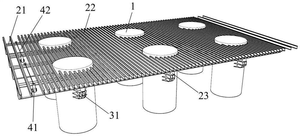
[0045] See figure 1 and figure 2 , a temporary bracket arranged using steel casings, including steel casings 1 arranged in a matrix, each row of the matrix includes more than two steel casings 1, and each column of the matrix includes more than two steel casings 1 ;

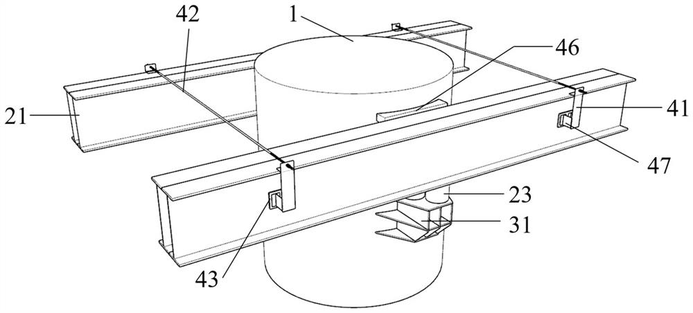
[0046] Both sides of each row of steel casings are horizontally supported by a corbel mechanism and arranged with transverse beams 21, and two adjacent transverse beams 21 are clamped and arranged on both sides of each row of steel casings by a clamping mechanism;

[0047] Longitudinal beams 22 are evenly arranged on the upper ends of the transverse beams 21;

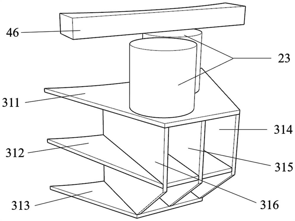
[0048] Each of the corbel mechanisms includes more than two corbels 31, and the opposite sides of each steel casing 1 are correspondingly fixedly installed with the corbels 31, and the upper end of each corbel 31 is vertically arranged to support the corresponding transverse beam. 21 more than two unloading sand barrels 23;

[0049] The clamping mecha...

Embodiment 2

[0064] The construction method of embodiment 1 temporary bracket, comprises the following steps:

[0065] Step 1: Remove the mud on the inner and outer walls of the steel casing 1 within the scope of the corbel 31, derust the wall within the scope of the steel casing 1, and weld the first layer of partitions 311 and the third layer of partitions 313 of the corbel 31 The elevation line is released and marked on the steel casing 1;

[0066] Step 2: After the corbel 31 is processed and formed by the steel structure processing plant, it is transported to the construction site, and the corbel 31 is lifted to the marked position by a crane, and welded and fixed on both sides of the steel casing 1;

[0067] Step 3: Fill the sand removal cylinder 23 with dry coarse sand, pour C30 concrete in the cylinder core, and perform preloading; after the preloading is completed, fix the sand removal cylinder 23 and the first layer of partitions 311 by spot welding, When multiple sand dumping tu...


PUM


Abstract

The invention relates to the technical field of constructional engineering, and particularly relates to a temporary bracket arranged by utilizing steel casings and a construction method thereof. The temporary bracket comprises the steel casings arranged in a matrix mode, wherein transverse beams are horizontally arranged on the two sides of each row of steel casings through bracket mechanisms in a supporting mode, and every two adjacent transverse beams are clamped and arranged on the two sides of each row of steel casings through clamping mechanisms; longitudinal beams are uniformly arranged at the upper ends of the transverse beams, each bracket mechanism comprises two or more brackets, and two or more unloading sand cylinders used for supporting the corresponding transverse beams are vertically arranged at the upper ends of the brackets; and a pair of limiting mechanisms is correspondingly arranged on the two opposite sides of each steel casing, the distance between a pair of limiting plates is adjusted by adjusting the locking positions of a pair of nuts on a screw rod, so that a pair of square cushion blocks abut against the corresponding side faces of every two adjacent transverse beams. Therefore, the brackets welded by the existing steel casings are utilized, so that embedded parts are prevented from being arranged on a pile body, the structure of the pile body is not affected, and the appearance quality of pile body concrete is not affected after the temporary bracket is disassembled.

Description

technical field [0001] The invention relates to the technical field of construction engineering, in particular to a temporary bracket arranged by a steel casing and a construction method thereof. Background technique [0002] High pile cap pile foundations are commonly used in sea-crossing and river-crossing bridge projects, and are also widely used in complex geological and terrain conditions. The construction of the part of the high pile cap higher than the ground surface or water surface needs to build a temporary bracket as a construction platform for operation. The conventional method is to use a floor bracket or an anchor bracket. Floor-mounted brackets have high requirements on the bearing capacity of the foundation and are often limited by terrain conditions; anchored brackets require pre-embedded section steel or reserved slots on the pile body, and use welded section steel as a support bracket, which is difficult to install and dismantle. It has a great influence ...

Claims


Application Information

Patent Timeline
IPC IPC(8): E02D27/14E02D27/42E02D5/66E02D15/02
CPCE02D27/14E02D27/42E02D5/66E02D15/02E02D2300/002E02D2300/0029
Inventor 张立兵汪亦显欧阳继业李健李娴徐健跃郭永刚汤瑞王凯钟剑王伟琚琳
Owner ANHUI ROAD & BRIDGE GRP
Learn More