Water kinetic energy device without energy consumption and energy storage method

A hydrokinetic energy-free technology, which is applied in household refrigeration devices, hydroelectric power generation, engine components, etc., can solve the problems of large energy loss, immature water utilization system, inconvenient circulation movement, etc., to achieve electric energy storage and facilitate promotion The effect of using and raising the temperature

Pending Publication Date: 2021-12-10
渠中权
View PDF0 Cites 0 Cited by
  • Summary
  • Abstract
  • Description
  • Claims
  • Application Information

AI Technical Summary

Problems solved by technology

[0003] At present, the consumption of clean energy is increasing, and people are paying more and more attention to the utilization of renewable energy, including water energy. How to improve the energy utilization rate of water energy and make full use of water energy has become the main solution. Traditionally, water flow is used. The way of directly impacting the turbine consumes a lot of energy, and it is not convenient to circulate in a state of no energy consumption, resulting in an immature water utilization system

Method used


Image

  • Water kinetic energy device without energy consumption and energy storage method
  • Water kinetic energy device without energy consumption and energy storage method
  • Water kinetic energy device without energy consumption and energy storage method

Examples


Embodiment

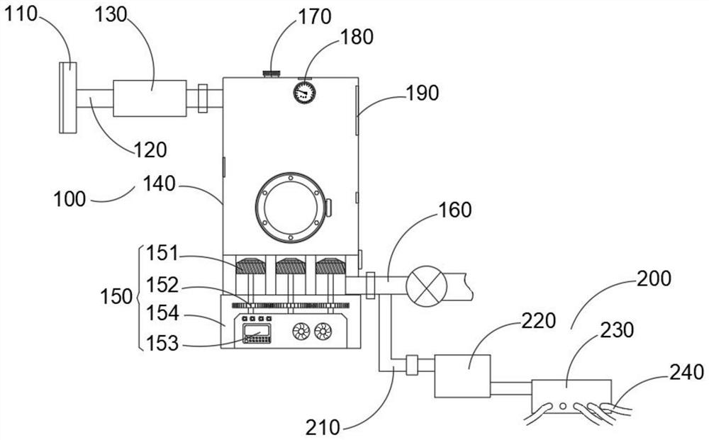
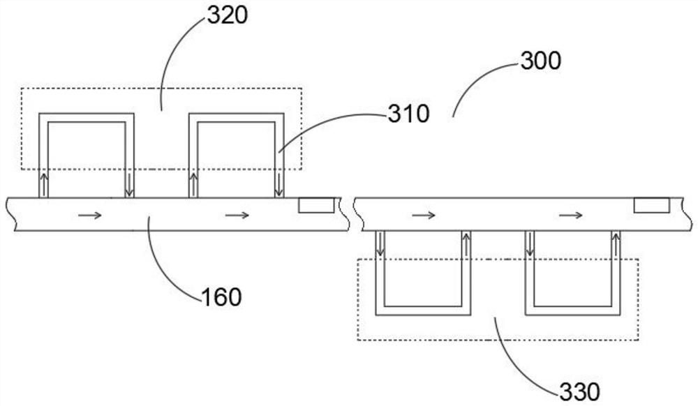
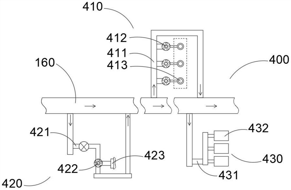
[0046] combine Figure 1-5As shown, the non-energy consumption and hydrokinetic energy device provided by the present invention includes: a water energy mechanism 100, a water intake mechanism 200, a temperature control mechanism 300, and a distribution mechanism 400. The head 110, the water inlet pipe 120 for transporting the water source introduced into the water inlet head 110, the filter 130 for filtering the water source for delivery, the water storage tank group 140 for storing the water delivery source, and the water storage tank group 140 for The conversion assembly 150 for energy conversion, the outlet pipe 160 for discharging the water source to the upstream of the dam, the exhaust valve 170 arranged on the top of the water storage tank group 140, and the pressure sensor 180 installed on the water storage tank group 140 for pressure detection And the water level detector 190 used to detect the water level in the water storage tank group 140 is used for technologies s...


PUM


Abstract

The invention belongs to the technical field of water kinetic energy and energy storage, and particularly relates to a water kinetic energy device without energy consumption and an energy storage method. The device comprises a water energy mechanism, a water taking mechanism, a temperature control mechanism, and a separate use mechanism; the water energy mechanism comprises a water inlet head arranged at the downstream of a dam for introducing a water source, a water inlet pipe for conveying the water source introduced by the water inlet head, a filter for filtering the conveyed water source, a water storage tank group for storing the conveyed water source, a conversion assembly mounted to the water storage tank group for energy conversion, a water outlet pipe for discharging the water source to the upstream of the dam, and an exhaust valve arranged at the top of the water storage tank group. In the invention, water flow in the downstream of a river dam can be introduced by the water energy mechanism, a negative pressure state is formed in the water storage tank group, and water is discharged to the upstream of the dam by using potential energy, so as to achieve energy-consumption-free conveying; water kinetic energy of the water flow is converted into electric energy by the conversion assembly; through the arrangement of the conversion assembly, the water flow can fully drive a vortex cylinder to rotate, so as to achieve storage of the electric energy.

Description

technical field [0001] The invention relates to the technical field of hydrokinetic energy and energy storage, in particular to a non-energy consumption, hydrokinetic energy device and an energy storage method. Background technique [0002] Water kinetic energy without energy consumption refers to the conversion of water energy into other energy sources for people to use, and the excess energy can be stored. Based on the law of energy conservation and conversion, various mechanical energies (kinetic energy, pressure potential energy, Positional potential energy) and mutual conversion between them, while overcoming water flow resistance, a part of the mechanical energy must be lost and converted into the heat energy of the liquid in equal amounts. The relationship is complicated, and the energy conservation and conversion relationship is generally only studied for the constant flow. [0003] At present, the consumption of clean energy is increasing, and people are paying mor...

Claims


Application Information

Patent Timeline
Patent Type & Authority Applications(China)
IPC IPC(8): F03B13/08F03B11/08A01K63/04F25D31/00
CPCF03B13/08F03B11/08A01K63/042F25D31/005Y02E10/20
Inventor 徐礼红渠中权王建美冯丽美渠中胜冯丽京
Owner 渠中权
Why Eureka
Try Eureka