
Heat exchanger with internal circulating rotational flow mechanism

An internal circulation and heat exchanger technology, applied in the direction of heat exchanger type, heat exchanger shell, indirect heat exchanger, etc., can solve the problems of unadjustable heat exchange stroke, inability to filter heat conduction fluid, and low heat exchange efficiency, etc. Achieve the effect of facilitating later maintenance, improving purity, and improving heat exchange efficiency

Pending Publication Date: 2021-12-10
江苏格安德环保工程科技有限公司
View PDF0 Cites 0 Cited by
  • Summary
  • Abstract
  • Description
  • Claims
  • Application Information

AI Technical Summary

Problems solved by technology

[0006] The technical problem to be solved by the present invention is: in order to solve the problems existing in the above-mentioned background technology, an improved heat exchanger with an internal circulation swirl mechanism is provided to solve the problem that most of the traditional gas heat exchangers have simple and fixed structures and cannot be assembled and disassembled. , the flow rate of the internal heat exchange fluid is fixed, the heat exchange stroke cannot be adjusted, the heat exchange efficiency is not high, and the heat transfer fluid cannot be filtered during the heat exchange, and regular cleaning and maintenance are required, which is time-consuming and laborious, and the problem of high later cost

Method used


Image

  • Heat exchanger with internal circulating rotational flow mechanism
  • Heat exchanger with internal circulating rotational flow mechanism
  • Heat exchanger with internal circulating rotational flow mechanism

Examples


Embodiment Construction

[0026] The present invention is described in further detail now in conjunction with accompanying drawing. These drawings are all simplified schematic diagrams, which only illustrate the basic structure of the present invention in a schematic manner, so they only show the configurations related to the present invention.

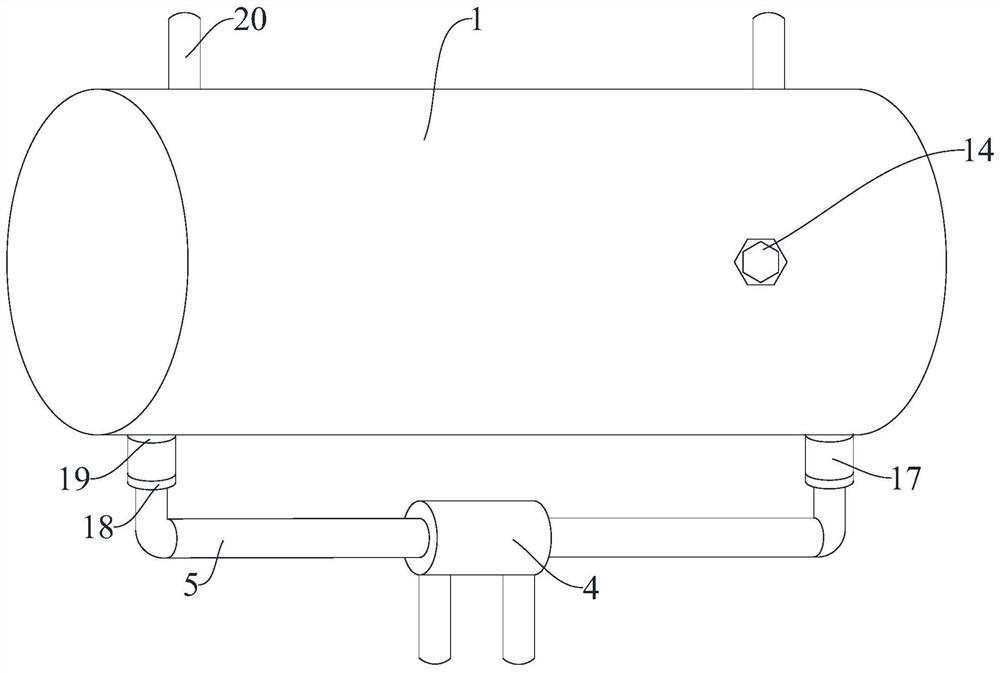
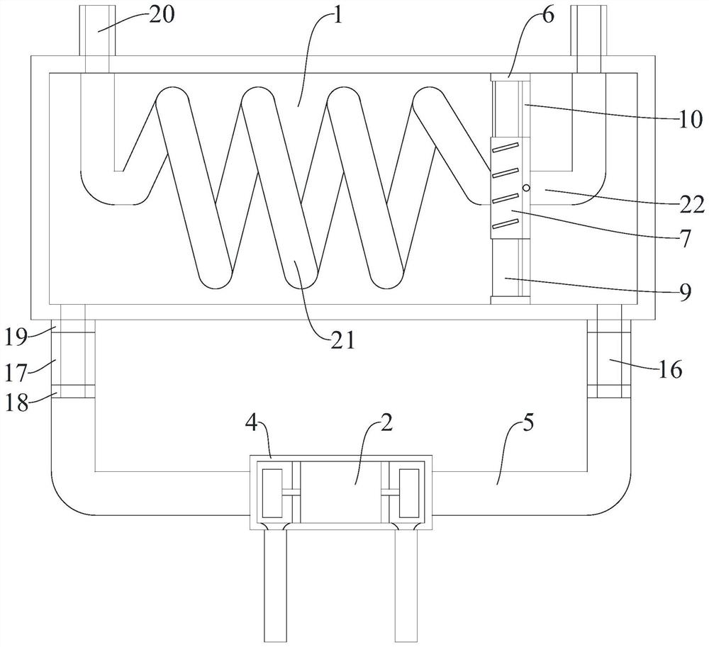
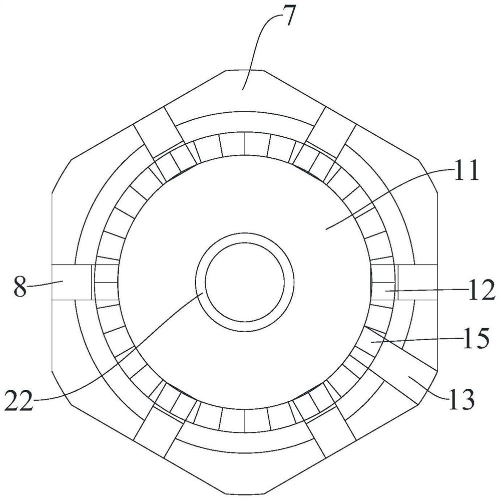
[0027] figure 1 , figure 2 with image 3 A heat exchanger with an internal circulation swirl mechanism is shown, including a horizontal external heat exchange cylinder 1 and an electric circulating water pump 2, and a bottom return for installing the electric circulating water pump 2 is arranged in parallel at the lower end of the horizontal external heat exchange cylinder 1. The water cylinder 4 and the two ends of the bottom return cylinder 4 are fixedly connected to the interior of the horizontal external heat exchange cylinder 1 through the L-shaped structure lateral circulation water pipe 5, and the two sides of the lower end of the bottom return cylin...


PUM


Abstract

The invention relates to the technical field of gas heat exchange equipment, in particular to a heat exchanger with an internal circulating rotational flow mechanism. The heat exchanger comprises a transverse external heat exchange cylinder and an electric circulating water pump. According to the heat exchanger with the internal circulating rotational flow mechanism, the angle-adjustable rotational flow mechanism adjusted by a lateral adjusting device is fixedly connected to the inner side surface of the transverse external heat exchange cylinder through a lateral assembling ring, the flow speed can be adjusted, rotational flow can be formed, internal heat is more uniform, and therefore the heat exchange efficiency is improved; a circulating heat exchange runner is formed in the heat exchanger, so that the internal heat exchange efficiency is higher; a metal filter cartridge with a built-in detachable filter element is fixedly connected to the connecting end of a lateral circulating water pipe and the transverse external heat exchange cylinder in a threaded mode, so that the later use cost is lowered; and the transverse external heat exchange cylinder and the lateral circulating water pipe fixedly communicate with each other through a bottom water return cylinder and are assembled and disassembled in a detachable thread assembly mode, and filter element replacement and later maintenance are facilitated.

Description

technical field [0001] The invention relates to the technical field of gas heat exchange equipment, in particular to a heat exchanger with an internal circulation swirl mechanism. Background technique [0002] The gas heat exchanger is an energy-saving device that realizes heat transfer between materials between two or more fluids at different temperatures. It transfers heat from a fluid with a higher temperature to a fluid with a lower temperature, so that the fluid temperature reaches The indicators specified in the process can meet the needs of process conditions, and it is also one of the main equipment to improve energy utilization. [0003] The heat exchanger industry involves HVAC, pressure vessels, reclaimed water treatment equipment, chemical, petroleum and other industries, forming an industrial chain with each other. Mainly concentrated in petroleum, chemical industry, metallurgy, electric power, shipbuilding, central heating, refrigeration and air conditioning, ...

Claims


Application Information

Patent Timeline
IPC IPC(8): F28D7/02F28F9/24F28F19/01F28F9/26
CPCF28D7/02F28F9/24F28F19/01F28F9/26F28F2275/20
Inventor 秦晓涛秦华明赵小松
Owner 江苏格安德环保工程科技有限公司
Learn More