High-performance rotor based on electric transmission system

A high-performance, electric drive technology, applied in electric components, electrical components, electromechanical devices, etc., can solve the problems of poor rotor high-speed performance, high rotor eddy current loss, poor assembly process, etc., to improve mechanical strength, improve performance, improve The effect of reliability

Pending Publication Date: 2021-12-10
JIANGLU MACHINERY & ELECTRONICS GROUP
View PDF4 Cites 0 Cited by
  • Summary
  • Abstract
  • Description
  • Claims
  • Application Information

AI Technical Summary

Problems solved by technology

[0002] As the application of electric transmission system becomes more and more extensive, the performance requirements for the drive motor for electric transmission system are also getting higher and higher. The original electric transmission system motor has relatively large static braking torque, poor rotor high-speed performance, and poor assembly process. The performance is poor, the eddy current loss generated by the rotor itself is high, the additional torque generated by the harmonic magnetic field is large, and the electromagnetic vibration and noise have an impact on the system

Method used


Image

  • High-performance rotor based on electric transmission system
  • High-performance rotor based on electric transmission system
  • High-performance rotor based on electric transmission system

Examples


Embodiment 1

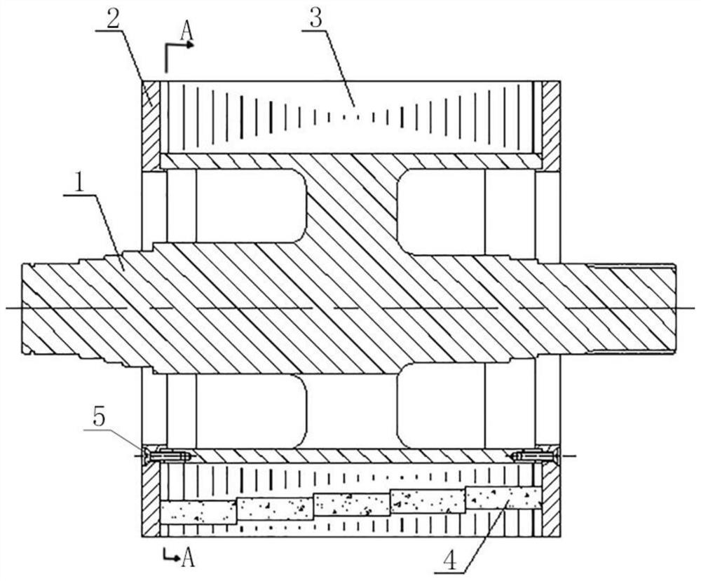
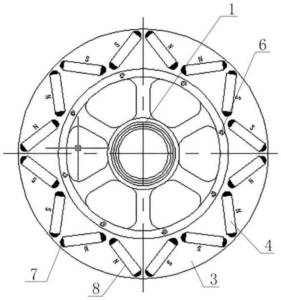
[0027] Such as Figure 1-7 As shown, a high-performance rotor based on an electric transmission system includes a rotating shaft 1, a rotor baffle 2 and a rotor core 3. After the rotating shaft 1 is sleeved with several sections of rotor core 3, and the rotor baffle 2 is used to separate The two ends of the three groups of fixed rotor cores are optimized to reduce the cogging torque and pulsation of the entire electrical system and improve the performance of the entire system by optimizing the structural performance parameters of the high-speed drive motor rotor used in the electric drive system.

Embodiment 2

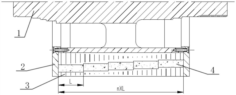
[0029] On the basis of Embodiment 1, the rotor core 3 is a silicon steel sheet with a ring structure, and magnetic steel grooves 8 are equidistantly arranged on the ring surface, and permanent magnets 4 are arranged in the magnetic steel grooves 8, and the permanent magnets 4 are placed in the Segmentation of the substrate state can effectively reduce the eddy current loss of the permanent magnet 4, reduce the motor loss, and improve the motor efficiency and magnetic field weakening capability.

Embodiment 3

[0031] On the basis of Embodiment 2, the length of the permanent magnet 4 corresponds to the thickness of the rotor core 3, and the entire rotor is segmented into n block, and install the magnetized permanent magnet 4 into the magnetic steel groove 8, which effectively improves the manufacturability of rotor assembly.


PUM


Abstract

The invention discloses a high-performance rotor based on an electric transmission system, relates to the technical field of high-performance rotors, and solves the technical problems that an existing motor is large in static braking torque, poor in rotor high-speed performance and poor in assembly manufacturability, the eddy-current loss generated by the rotor itself is high, additional torque generated by the harmonic magnetic field is relatively large, and electromagnetic vibration and noise have influence on the system at same time. The high-performance rotor comprises a rotating shaft, rotor baffles and rotor cores, wherein after the rotating shaft is sleeved with a plurality of sections of rotor cores, the two ends of the rotor cores are fixed through the rotor baffles respectively, the rotor cores are silicon steel sheets of an annular structure, magnetic steel grooves are formed in the ring surface at equal intervals, and permanent magnets are arranged in the magnetic steel grooves. By optimizing the structural performance parameters of the high-speed driving motor rotor for the electric transmission system, the cogging torque and pulsation of the whole electric system are reduced, and the performance of the whole system is improved.

Description

technical field [0001] The present invention relates to the technical field of rotors, more specifically to the technical field of high-performance rotors based on electric drive systems. Background technique [0002] As the application of electric transmission system becomes more and more extensive, the performance requirements for the drive motor for electric transmission system are also getting higher and higher. The original electric transmission system motor has relatively large static braking torque, poor rotor high-speed performance, and poor assembly process. The performance is poor, the eddy current loss generated by the rotor itself is high, the additional torque generated by the harmonic magnetic field is large, and the electromagnetic vibration and noise have an impact on the system. [0003] The application of a motor rotor that can effectively reduce electromagnetic vibration and noise, has small loss, good high-speed performance, and small static moment has be...

Claims


Application Information

Patent Timeline
Patent Type & Authority Applications(China)
IPC IPC(8): H02K1/27H02K1/28
CPCH02K1/276H02K1/28
Inventor 陈建文王艳艳朱刚莫竟芳肖强陈达蔡兵兵
Owner JIANGLU MACHINERY & ELECTRONICS GROUP
Why Eureka
Try Eureka