Motorized spindle grinding head
A technology of electric spindle and grinding head, which is applied in the direction of grinding machines, grinding machine parts, grinding/polishing equipment, etc. It can solve the problems of increased feed adjustment resistance, inability to overcome resistance, complex structure, etc., to reduce torque and lighten Effects of weight and shortened moment arm length
- Summary
- Abstract
- Description
- Claims
- Application Information
AI Technical Summary
Problems solved by technology
Method used
Image

Examples
Embodiment 1
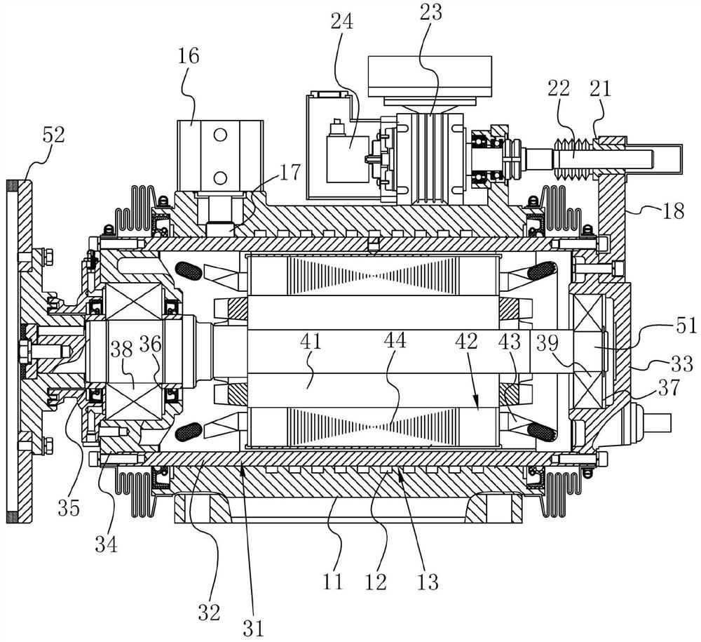
[0043] refer to figure 2 , an electric spindle grinding head, including a grinding head seat 11, a grinding head shaft 51, a grinding wheel 52, a feeding device, a sliding sleeve 31, a stator 42 and a rotor 41. The grinding head base 11 is provided with a fixed end, which is used to connect with the frame of the edge grinding machine, so as to realize the installation of the electric spindle grinding head on the edge grinding machine, realize the function of fixing the grinding head base 11, and facilitate the use of the grinding head. The effect of edge machine processing.
[0044] The grinding head seat 11 is sheathed on the outer wall of the sliding sleeve 31 , the sliding sleeve 31 slides axially with the grinding head seat 11 and engages in the circumferential direction, and the feeding device is respectively connected to the grinding head seat 11 and the sliding sleeve 31 . The feeding device includes a connecting plate 18, a nut 21, a screw rod 22 and a driving mechan...
Embodiment 2
[0072] refer to Figure 5 , an electric spindle grinding head, the difference from Embodiment 1 is that the feeding device includes a connecting plate 18, a nut 21, a screw rod 22 and a driving mechanism, the connecting plate 18 is fixedly mounted on the sliding sleeve 31, and the driving mechanism is fixedly mounted on the The connecting plate 18 and the screw mandrel 22 are connected to the driving mechanism, the nut 21 is fixedly connected to the grinding head seat 11 , and the screw mandrel 22 is screwed to the nut 21 . The drive mechanism includes a motor 24 and a reducer 23, the reducer 23 is fixedly installed on the connecting plate 18, the motor 24 shell is fixedly connected with the reducer 23 shell, the output shaft of the motor 24 is fixedly connected with the reducer 23 input shaft, and the reducer 23 output shaft It is fixedly connected with the screw rod 22.
[0073] The driving mechanism drives the screw rod 22 to rotate, so that the screw rod 22 moves on the n...
Embodiment 3
[0078] refer to Figure 6 , an electric spindle grinding head, which differs from Embodiment 2 in that the driving mechanism includes a reducer 23 and a vertical handwheel 25, and the vertical handwheel 25 is located above the reducer 23 and is fixedly connected to the input shaft of the reducer 23.
[0079] This embodiment has the following advantages:
[0080] By turning the vertical hand wheel 25 above the reducer 23, the reducer 23 can drive the screw mandrel 22 to rotate. The setting of the speed reducer 23 plays a role in adjusting the rotating speed, so as to achieve the effect of conveniently controlling the rotating speed of the screw mandrel 22 and adjusting the position of the sliding sleeve 31 conveniently.
PUM
 Abstract
Description
Claims
Application Information
 - Generate Ideas
- Intellectual Property
- Life Sciences
- Materials
- Tech Scout
- Unparalleled Data Quality
- Higher Quality Content
- 60% Fewer Hallucinations
Browse by: Latest US Patents, China's latest patents, Technical Efficacy Thesaurus, Application Domain, Technology Topic, Popular Technical Reports.
© 2025 PatSnap. All rights reserved.Legal|Privacy policy|Modern Slavery Act Transparency Statement|Sitemap|About US| Contact US: help@patsnap.com