
A Configuration Method of Low Shear Strength Grouting Material in Shield Excavation Gap

A technology of grouting materials and configuration methods, which is applied in earthwork drilling, shaft equipment, wellbore lining, etc., can solve the problems of filling material loss, poor workability, and low strength, so as to reduce material loss, prevent segregation, and control The effect of ground deformation

Active Publication Date: 2022-02-08
BEIJING URBAN CONSTR GROUP +2
View PDF0 Cites 0 Cited by
  • Summary
  • Abstract
  • Description
  • Claims
  • Application Information

AI Technical Summary

Problems solved by technology

[0006] (1) The initial strength of the filling material is relatively low, and it cannot interact with the soil outside the shield shell in time, or the setting of the initial setting time is unreasonable and other factors cannot achieve real filling;
[0007] (2) The proportion of filling materials is unreasonable, which may cause the filling material to have too good fluidity, flow to the cutter head and consolidate, causing the cutter head to twist greatly, or the workability is poor, and the filling material segregates, resulting in filling For material loss, the strength and impermeability of the filling material should be improved for the fast approaching portal and communication channel;
[0008] (3) For different formations, the effect of filling materials may be different
If the filling effect is controlled by the filling amount, it may not be able to form an effective support for the soil around the shield shell due to reasons such as low strength of the filling material or high self-shrinkage

Method used

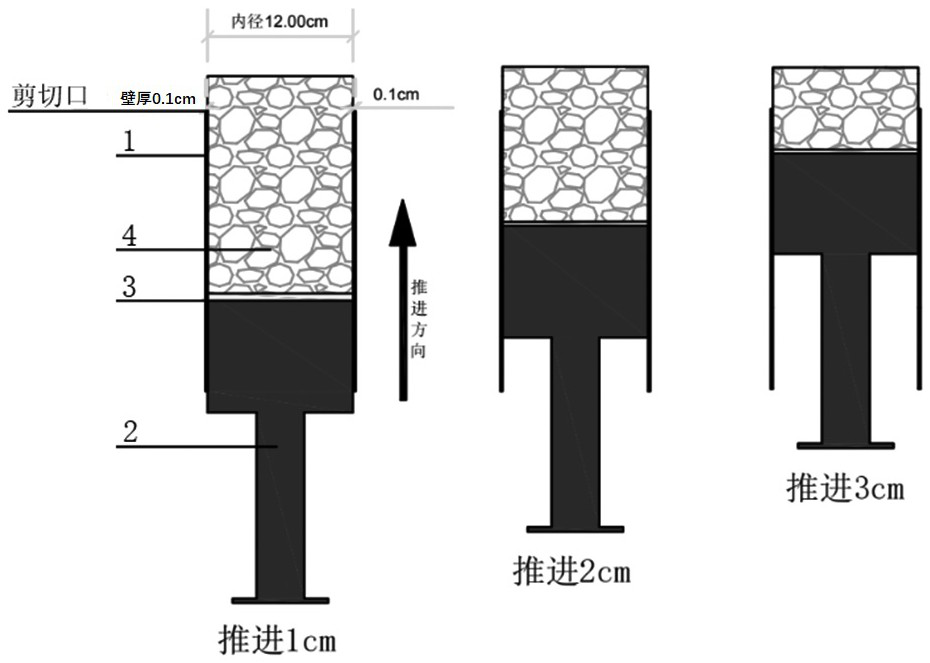
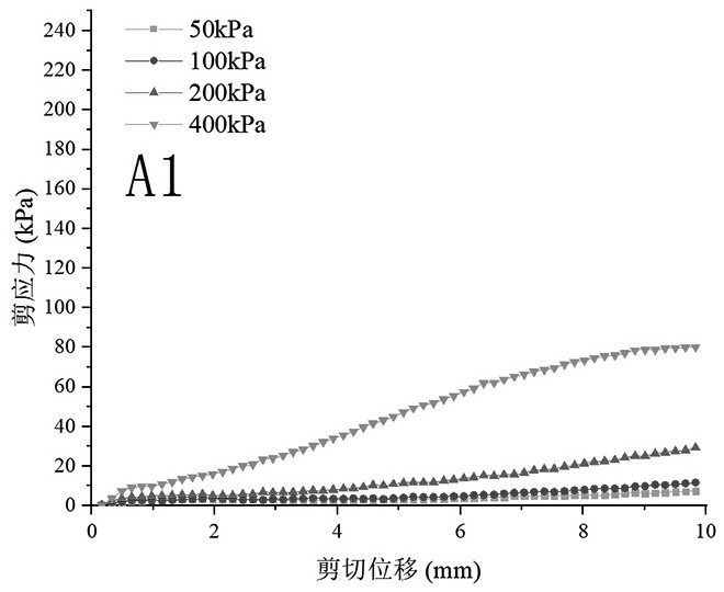
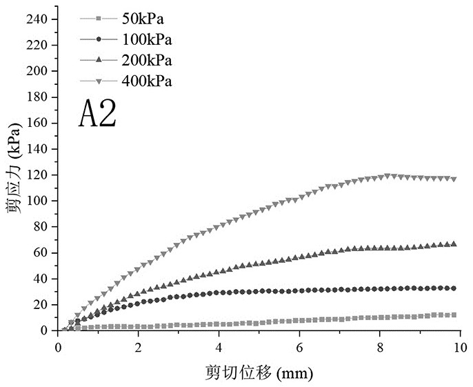

Image

  • A Configuration Method of Low Shear Strength Grouting Material in Shield Excavation Gap
  • A Configuration Method of Low Shear Strength Grouting Material in Shield Excavation Gap
  • A Configuration Method of Low Shear Strength Grouting Material in Shield Excavation Gap

Examples


Embodiment Construction

[0056] In order to make the purpose, technical solutions and advantages of the embodiments of the present invention more clear, the present invention will be further described in detail below in conjunction with the embodiments and the accompanying drawings. Here, the exemplary embodiments and descriptions of the present invention are used to explain the present invention, but not to limit the present invention.

[0057] In describing the present invention, it is to be understood that the terms "comprises / comprising", "consisting of" or any other variation thereof are intended to cover a non-exclusive inclusion such that a product, device, A process or method includes not only those elements, but may also include other elements not expressly listed, or elements inherent in such a product, apparatus, process, or method, as required. Without further limitations, an element defined by the phrase "comprising / comprising...", "consisting of... does not exclude the presence of additi...


PUM

PropertyMeasurementUnit
thicknessaaaaaaaaaa
melting pointaaaaaaaaaa
shear stressaaaaaaaaaa

Abstract

The invention discloses a configuration method of a low-shear strength grouting material for a shield excavation gap, which comprises the following steps: selecting a grouting material; preliminary designing multiple groups of grouting materials with different water-cement ratios and multiple groups of different swelling ratios ; Make multiple groups of grouting material specimens; test the shear strength of each group of specimens to obtain the optimal water-cement ratio and optimal swelling ratio of the grouting material; add bentonite and water to the mixer according to the optimal swelling ratio Stir inside to make it fully mixed evenly, and then let it stand to make it fully expanded; measure the water glass with the required Baume degree, add it to the expanded bentonite slurry, and stir evenly; add cement powder, continue to stir evenly, and configure Finish. The invention studies the filling problem of the excavation gap in shield construction, and can solve the problem that the conventional shield grouting material locks the shield; adopts a new filling material configuration method to meet the pumping requirements in the grouting equipment, At the same time, it has high shear strength.

Description

technical field [0001] The invention belongs to the technical field of shield tunnel construction, and in particular relates to shield tunnel grouting technology, in particular to a configuration method for low shear strength grouting materials in shield tunnel excavation gaps. Background technique [0002] In addition to the grouting material, the grouting effect is also related to the grouting parameters such as the grouting pressure and grouting time in the shield construction process. In the existing research, experts and scholars have studied the grouting diffusion radius, Factors such as the strength of the stone body after grouting were studied, so as to obtain the relationship between the grouting parameters and the filling effect. [0003] Yang Ping et al. used the indoor test method to conduct grouting experiments on sand and pebble formations, and concluded that the grouting pressure has the most significant impact on the slurry diffusion radius, followed by the p...

Claims


Application Information

Patent Timeline
Patent Type & Authority Patents(China)
IPC IPC(8): C04B28/26E21D11/10C04B111/70
CPCC04B28/26E21D11/10C04B2111/70C04B7/02C04B14/104
Inventor 张晋勋江华张汉栋张小燕武福美江玉生黄陆川周刘刚
Owner BEIJING URBAN CONSTR GROUP
Learn More