
Movable reservoir and construction process thereof

A construction technique and a technology of a water storage tank, which is applied to waterway systems, water supply devices, drainage structures, etc., can solve problems such as inability to realize simple disassembly, difficulty in installation and disassembly, and inability to realize modular installation, so as to achieve a safe and reliable overall structure, satisfying High water level requirements, suitable for mobile operations

Pending Publication Date: 2021-12-14
潍坊宝源塑料制品有限公司
View PDF0 Cites 0 Cited by
  • Summary
  • Abstract
  • Description
  • Claims
  • Application Information

AI Technical Summary

Problems solved by technology

The tank body of the concrete storage tank is made of reinforced concrete. The construction and maintenance period of the concrete storage tank is long and the cost is high. The inner wall of the tank is rough and easy to adhere to sediment. The tank body is a rigid facility and cannot be installed modularly. It cannot be moved, and the cost of dismantling after one-time use is high, which will cause a lot of construction waste
The steel plate cistern is made of steel plates welded into a cuboid to hold water. The bottom of the pool can be a concrete surface or a steel plate. The bottom plate and the four-sided vertical steel plates are fixed together to form a water storage space. The steel plate is usually used to obtain the stability of the overall structure. The thickness is about 10mm, the cost is high, and this overall structure cannot be easily disassembled, nor can it be carried around, especially for large-capacity reservoirs, it is difficult to install and disassemble

Method used


Image

  • Movable reservoir and construction process thereof
  • Movable reservoir and construction process thereof
  • Movable reservoir and construction process thereof

Examples


Embodiment Construction

[0038] In order to clearly illustrate the technical features of this solution, the present invention will be described in detail below through specific implementation modes and in conjunction with the accompanying drawings.

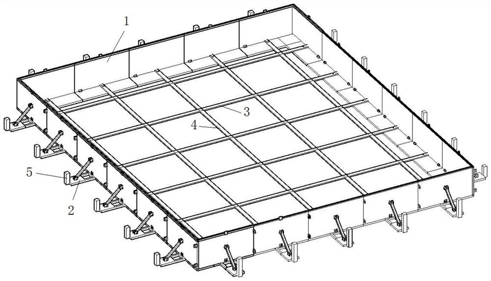
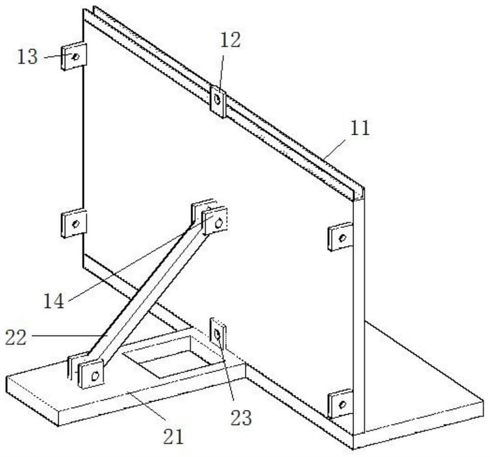
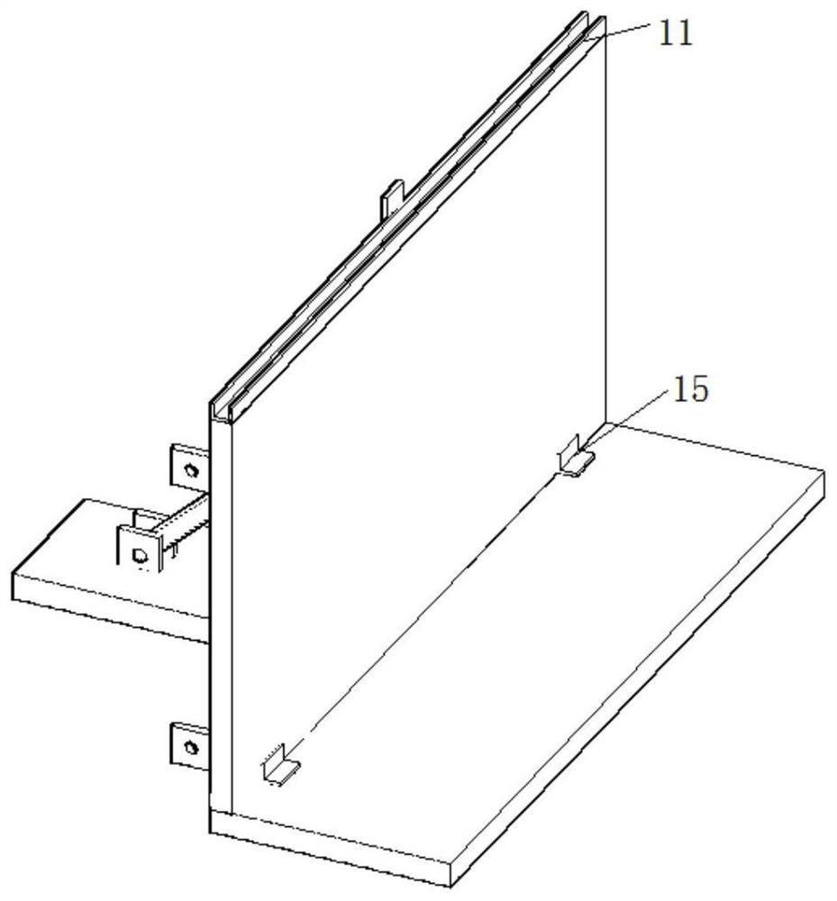
[0039] Such as figure 1 As shown, the embodiment of the present invention provides a movable sewage storage tank. The sewage storage tank mainly includes a pool structure with an open top formed by splicing a plurality of L-shaped plates 1. Two adjacent detachably connected between two L-shaped boards 1 .

[0040] The inner membrane used to hold water is hoisted in the pool structure, and the shape of the inner membrane should be similar to the inner structure of the pool body, and after the inner membrane is placed, the edge should protrude from the outside of the pool body structure to ensure that the water will not Through the flow to the interior of the pool structure.

[0041] The edge of the inner membrane is connected to the steel pipe. For examp...


PUM


Abstract

The invention discloses a movable reservoir and a construction process thereof, and belongs to the technical field of reservoirs. The reservoir comprises a reservoir body structure, wherein the reservoir body structure is formed by splicing a plurality of L-shaped plates, every two adjacent L-shaped plates are detachably connected, an inner film for containing water is arranged in the reservoir body structure, the edge of the inner film is connected with a steel pipe, a clamping groove capable of containing a steel pipe is formed in the top of each L-shaped plate, and the two opposite L-shaped plates in the reservoir body structure are connected through a tensioning steel wire rope. Compared with an existing cement and steel plate reservoir body structure, the reservoir has the advantages of low cost and convenience in installation and removal.

Description

Technical field: [0001] The invention belongs to the technical field of water storage tanks, and in particular relates to a movable water storage tank and a construction process thereof. Background technique: [0002] The cistern is a water storage facility built with artificial materials and has an anti-seepage effect. At present, the conventional products of sewage storage tanks are concrete storage tanks or steel storage tanks. The tank body of the concrete storage tank is made of reinforced concrete. The construction and maintenance period of the concrete storage tank is long and the cost is high. The inner wall of the tank is rough and easy to adhere to sediment. The tank body is a rigid facility and cannot be installed modularly. It cannot be moved, and the cost of dismantling after one-time use is high, which will cause a lot of construction waste. The steel plate cistern is made of steel plates welded into a cuboid to hold water. The bottom of the pool can be a con...

Claims


Application Information

Patent Timeline
Patent Type & Authority Applications(China)
IPC IPC(8): E03F5/10E04H7/02
CPCE03F5/10E04H7/02
Inventor 闫杰龙
Owner 潍坊宝源塑料制品有限公司
Learn More