
Hydro-pneumatic suspension damping system of underground multifunctional service vehicle

A technology of oil and gas suspension and shock absorption system, which is applied to shock absorbers, gas-liquid shock absorbers, springs/shock absorbers, etc. problem, to achieve the effect of stabilizing the flow and ensuring the shock absorption effect

Active Publication Date: 2021-12-14
QINGDAO FAMBITION HEAVY MASCH CO LTD
View PDF0 Cites 0 Cited by
  • Summary
  • Abstract
  • Description
  • Claims
  • Application Information

AI Technical Summary

Problems solved by technology

[0003] However, when the mine car travels in the mine road or mine, the smoothness of the road is poor. The recovery speed of the existing oil-gas suspension recovery stroke is affected by the diameter of the cross-section of the damping hole. The recovery speed of the oil-gas suspension is slow, which affects the amplitude of the compression stroke. Damping effect of oil-air suspension

Method used


Image

  • Hydro-pneumatic suspension damping system of underground multifunctional service vehicle
  • Hydro-pneumatic suspension damping system of underground multifunctional service vehicle
  • Hydro-pneumatic suspension damping system of underground multifunctional service vehicle

Examples


Embodiment 1

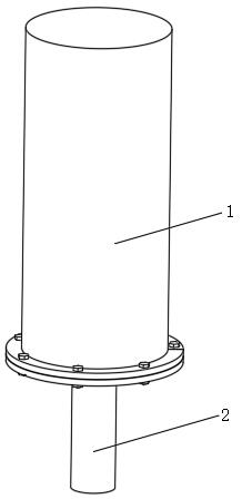
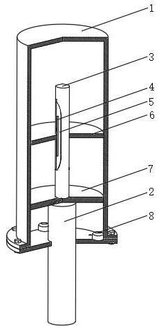
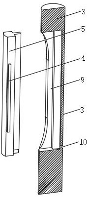
[0034] Example 1: Please refer to Figure 1-5 , this embodiment discloses an oil-gas suspension damping system for an underground multifunctional service vehicle, which includes a connecting rod 2, a piston 7, and a cylinder 1 with an open lower end, the outer peripheral side of the piston 7 is in sliding and sealed connection with the inner wall of the cylinder 1, and the piston 7 The lower side is connected to the upper end of the connecting rod 2, and the inner wall of the cylinder 1 is fixed with a partition plate 6, which is located above the piston 7, and the partition plate 6 is provided with a vertical damping hole, and a sliding rod is provided on the damping hole for sliding sealing. 3. The lower end of the sliding rod 3 is connected to the upper side of the piston 7. When the piston 7 moves up and down, the piston 7 drives the sliding rod 3 to move up and down along the damping perforation. The upper and lower ends of the sinking groove are all closed, and the inner...

Embodiment 2

[0047] Embodiment two: if Figure 6-9 As shown, this embodiment discloses an oil-gas suspension damping system for an underground multifunctional service vehicle. There is an adjustment assembly, the adjustment assembly includes a first permanent magnet 11, a bracket 17 and a sleeve 14 sleeved on the slide rod 3, the inner wall of the sleeve 14 is threaded to the lower part of the outer peripheral side of the slide rod 3, and the lower end of the sleeve 14 is connected to the piston 7 The upper sides are connected by rotating parts. The rotating parts include but not limited to bearings or rotating pin rings. The outer peripheral side of the sleeve 14 is fixed with the first permanent magnet 11 through the bracket 17;

[0048] A drive mechanism 12 is installed on the top of the connecting rod 2, and a second permanent magnet 13 corresponding to the first permanent magnet 11 is installed on the drive mechanism 12.

[0049] Furthermore, the lower part of the sleeve 14 is provid...

Embodiment 3

[0055] Embodiment three: as Figure 6 with Figure 7 As shown, this embodiment discloses an oil-gas suspension damping system for an underground multifunctional service vehicle. hole, the upper side of the piston 7 is fixed with a guide rod 16, and the upper part of the guide rod 16 is slidably engaged with the clamping hole. The outer peripheral side is provided with a vertical concave groove along the vertical direction or there is a gap between the guide rod 16 and the clamping hole to realize the flow of oil inside and outside the clamping hole. The sliding rod 3 enables the guide rod 16 to move up and down and cannot go around the vertical The shaft rotates and the position of the slide rod 3 relative to the piston 7 is adjusted by means of an adjustment assembly.

[0056] In another preferred solution, the horizontal cross section of the sliding rod 3 is a non-circular plane.


PUM


Abstract

The invention disclose a hydro-pneumatic suspension damping system of an underground multifunctional service vehicle. The hydro-pneumatic suspension damping system comprises a connecting rod, a piston and a cylinder barrel, the peripheral side of the piston is in sliding sealing connection with the inner wall of the cylinder barrel, the lower side of the piston is connected with the upper end of the connecting rod, a partition plate located above the piston is fixed to the inner wall of the cylinder barrel, and a damping through hole is formed in the partition plate; a sliding rod penetrates through the damping through hole in a sliding and sealing mode, the lower end of the sliding rod is connected with the upper side of the piston, an inner sunken groove is formed in the peripheral side of the sliding rod in the length direction of the sliding rod, a guide deep groove is formed in the inner sunken groove in the length direction of the inner sunken groove, and a sliding inserting rod is installed in the guide deep groove in a sliding and sealing mode; and a liquid guide hole communicating the interior and exterior of the lower portion of the guide deep groove is formed in the peripheral side of the sliding rod. According to the hydro-pneumatic suspension damping system, different oil damping effects in the compression stroke and the recovery stroke are achieved, rapid resetting of the hydro-pneumatic suspension damping system in the recovery stroke is achieved, the amplitude of the compression stroke is guaranteed, the damping effect of the hydro-pneumatic suspension damping system is guaranteed, and the change of oil flowing damping caused by the fact that oil is pressed and heated is reduced.

Description

technical field [0001] The invention relates to the technical field of suspension, in particular to an oil-gas suspension shock absorption system for an underground multifunctional service vehicle. Background technique [0002] When the single-chamber oil-air suspension is in the compression stroke, the piston rod assembly extends into the cylinder, the oil in the cylinder is squeezed, and the oil flows through the damping hole, the damping force is generated by the oil flowing through the damping hole, and the elastic force is generated by the oil flowing through the damping hole. Compressed gas (nitrogen, argon and other inert gases) is generated, and as the oil flow rate increases, the damping force provided by the damping hole increases non-linearly, and the vibration of the vehicle can be quickly reduced; when the stroke is restored, the piston rod assembly is pulled away from the cylinder , so that the volume in the cylinder expands, and the oil flows back from the cav...

Claims


Application Information

Patent Timeline
IPC IPC(8): F16F9/06F16F9/32F16F9/516F16F9/52
CPCF16F9/061F16F9/516F16F9/52F16F9/3207F16F9/3242
Inventor 候军强罗祥齐吉富崔凯凯刘鑫李达
Owner QINGDAO FAMBITION HEAVY MASCH CO LTD
Learn More