Optical zero compensation method and system for laser tracking and aiming device

A technology of aiming device and laser tracking, which is applied in the direction of measuring device, radio wave measuring system, electromagnetic wave reradiation, etc., can solve the problems of difficult operation and long time-consuming cycle, and achieve avoiding repeated disassembly and assembly, simple and fast compensation, Labor saving effect

Pending Publication Date: 2021-12-14
HUBEI SANJIANG AEROSPACE WANFENG TECH DEV
View PDF0 Cites 0 Cited by
  • Summary
  • Abstract
  • Description
  • Claims
  • Application Information

AI Technical Summary

Problems solved by technology

In addition, the repeated disassembly and assembly of the detector also

Method used


Image

  • Optical zero compensation method and system for laser tracking and aiming device
  • Optical zero compensation method and system for laser tracking and aiming device
  • Optical zero compensation method and system for laser tracking and aiming device

Examples


Embodiment Construction

[0038] In order to make the object, technical solution and advantages of the present invention clearer, the present invention will be further described in detail below in conjunction with the accompanying drawings and embodiments. It should be understood that the specific embodiments described here are only used to explain the present invention, not to limit the present invention. In addition, the technical features involved in the various embodiments of the present invention described below can be combined with each other as long as they do not constitute a conflict with each other.

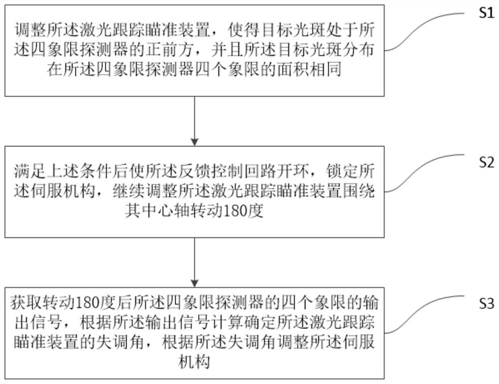
[0039] An optical zero position compensation method for a laser tracking and aiming device in an embodiment of the present invention is applied to a laser tracking and aiming device. The laser tracking and aiming device includes a four-quadrant detector, a servo mechanism and a feedback control loop. The feedback control loop is used to detect The output signal of the device adjusts the servo me...


PUM


Abstract

The invention discloses an optical zero compensation method and system for a laser tracking and aiming device. The method comprises the steps that: the laser tracking and aiming device is adjusted, so that target light spots are located right in front of a four-quadrant detector, and the areas of the target light spots distributed in four quadrants of the four-quadrant detector are the same; after the conditions are met, a feedback control loop is opened, a servo mechanism is locked, and the laser tracking and aiming device is continuously adjusted to rotate around the center axis by 180 degrees; output signals of the four quadrants of the four-quadrant detector after 180-degree rotation are obtained, the misalignment angle of the laser tracking and aiming device is calculated and determined according to the output signals, and the servo mechanism is adjusted according to the misalignment angle. According to the method and system of the invention, the error of the laser tracking and aiming device can be compensated simply and quickly, repeated disassembly and assembly can be avoided, and manpower is saved.

Description

technical field [0001] The invention belongs to the technical field of laser testing, and more particularly relates to an optical zero compensation method and system for a laser tracking and aiming device. Background technique [0002] In the laser aiming device, the four-quadrant detector is the key "eye" of photoelectric conversion. Each quadrant of the four-quadrant detector is functionally a photodiode. Next, the photodiode will generate electrons due to the stimulated absorption process, forming a current, and the magnitude of the formed current is proportional to the magnitude of the light energy it receives. The four photodiodes of the four-quadrant detector form four quadrants I, II, III, and IV. When the light beam is incident on the photosensitive surface of the four-quadrant detector, the actual output of the four-quadrant detector is the converted voltage signal. [0003] In the aiming device, the target laser signal is focused on the detector through the optica...

Claims


Application Information

Patent Timeline
IPC IPC(8): G01S7/497G01S17/66
CPCG01S7/497G01S17/66
Inventor 张正洋雷雯雯王明博胡冬粤刘俊池郭梦凡
Owner HUBEI SANJIANG AEROSPACE WANFENG TECH DEV
Why Eureka
Try Eureka